Automatic Liquid Mixing System
The Automatic Liquid Mixing System is a simple and efficient system that utilizes advanced PLC Ladder programming and a Timer. It automatically pours two liquids, Liquid A and Liquid B, into a container and blends them using a Stirrer for a specific time interval. Once the mixing process is complete, the mixture is transferred to another container. The system can be initiated by pressing the Start switch, and after one complete cycle, the start switch can be pressed again to restart the process. In case of critical conditions, there is an emergency switch to stop the process. The entire process is illustrated in the schematic diagram below, and the PLC program is organized using a Ladder diagram.

In the system, three 24V DC single-acting solenoid
valves (S1, S2, and S3) are used to control the flow of pressurized fluid.
Energizing the valve coil directs the fluid flow while de-energizing it
prevents the flow through the valve output port. S1 and S2 solenoid valves are
responsible for filling Liquid A and Liquid B into the mixing container,
respectively, while S3 functions to drain the liquid mixture into an external
storage container. Two normally open float switches, F1 and F2, are used to
monitor the liquid levels. F1 indicates the lower level, and F2 confirms the
upper level of the liquid inside the mixing container. Logic-1 is generated
when the water level touches F2, and Logic-1 is generated when the water
reaches the lower limit as detected by F1.
The Stirrer, driven by a 3-phase Induction motor
(M), effectively mixes Liquid A and Liquid B inside the container. A Contactor
(C) provides 3-phase AC power to activate the Induction motor. Once a certain
amount of liquids are poured into the container, the Stirrer starts rotating,
blending the mixture for a predetermined time. The time interval for Stirrer
rotation is controlled by Timer T1. After the mixing process is complete, the
motor stops, and the mixture is drained out to an external container through
solenoid valve S3. The duration of the liquid draining process is determined by
Timer T2.
The Ladder diagram represents the Input and Output elements of the system and their addresses. The following elements are included:
Input elements
- Start switch (SW1) = I0.1
- Emergency Stop switch (SW2) = I0.2
- Lower level Float switch (F1) = I0.3
- Upper-level Float switch (F2) = I0.4
Output elements
- Liquid-A inlet Solenoid (S1) = Q0.1
- Liquid-B inlet Solenoid (S2) = Q0.2
- Mixture outlet solenoid (S3) = Q0.3
- Stirrer motor Contactor (C) = Q0.4
Timers
- Stirrer ON Timer (200 seconds) = T1
- Mixture Outlet Timer (100 seconds) = T2
Interfacing of elements with PLC
The following picture illustrates the hardware configuration and interfacing of the different Input and Output elements with the PLC.

Ladder Programming
The previous diagram represents the hardware connections of various Input and Output devices with the PLC for the Automatic Liquid Mixing System. The Start switch (SW1) is a normally open push switch, the Emergency Stop switch is a normally closed type (NC), and both F1 and F2 are normally open float switches. The complete Ladder diagram of the Automatic Liquid Mixing System is explained in the following picture, with the program written in five different Rungs and subsequently interpreted step by step with individual Rungs.

The ladder diagram represents the logical illustration for triggering the output coil Q0.1. When Q0.1 is Logic-1, solenoid S1 will energize, causing Liquid-A to discharge into the mixing container. The push switch Input I0.1, emergency switch Input I0.2, and lower-level float switch Input I0.3 function in an AND Logic, where I0.1 and I0.2 are normally open (NO) contacts, and I0.3 is a normally closed (NC) contact. An emergency switch is typically a closed contact type that disconnects when activated or pressed. Output Q0.1 creates a latching circuit by employing an OR logic with Input I0.1.

Initially, input I0.3 will be in a deactivated state (as there is no liquid inside the container), and the status of I0.2 will be Logic-1 (as the emergency switch is always of the NC type). Pressing SW1, Input I0.1 will become Logic-1 and Output Q0.1 will also become Logic-1 since the lower-level float switch F1 is deactivated and used as an NC contact, satisfying the AND Logic and setting Q0.1 to Logic-1. The output functions as a latching circuit and remains activated even after releasing the switch SW1. The output coil Q0.1 energizes the solenoid valve S1, and Liquid-A starts to pour into the container. The pouring will continue as long as the lower-level float switch F1 is not activated. Upon activation of F1, the status of I0.3 will become Logic-0 (as it is used as an NC contact), and the status of Q0.1 will also become Logic-0, causing the pouring of Liquid-A to stop. The following three diagrams illustrate different states with the signal-flowing status of Rung-1.

Rung – 2
This diagram depicts the activation of the output coil Q0.2, allowing Liquid-B to enter the container by energizing solenoid valve S2. The logic used here is similar to Rung-1, where the lower-level float switch Input I0.3, emergency switch Input I0.2, and upper-level float switch Input I0.4 function using an AND Logic. Inputs I0.2 and I0.3 are normally open (NO) contacts, while I0.4 is used as a normally closed (NC) contact. Output Q0.2 also creates a latching circuit by employing an OR logic with Input I0.3.

As Input I0.3 activates (due to Liquid-A entering the container), its status becomes Logic-1, and Output Q0.2 also becomes Logic-1. As the upper-level float switch F2 is already deactivated and functions as an NC contact (I0.4), it satisfies the AND Logic, setting Q0.2 to Logic-1. Output Q0.2 also serves as a latching circuit, remaining in an activated state. With Q0.2 activated, it energizes solenoid valve S2, and Liquid-B starts entering the container. The flow of Liquid-B will continue as long as the upper-level float switch F2 is not activated. Upon activation of F2, the status of I0.4 will become Logic-0 (as it is used as an NC contact), and the status of Q0.2 becomes Logic-0, causing the flow of Liquid-B to stop. The following two diagrams illustrate different states with the signal-flowing status of Rung-2.

Rung – 3
Once the upper-level float switch F2 is activated, the entry of Liquid-B immediately stops, and the output coil Q0.4 energizes. In this rung, the upper-level float switch Input I0.4, emergency switch Input I0.2, and the timer contact T1 function using an AND Logic, where I0.2 and I0.4 are normally open (NO) contacts, and T1 is used as normally closed (NC) contact. T1 is an ON Delay Timer with a time interval of 200 seconds.

The timer used here is of the ON delay type, and initially, the status of the T1 contact will be Logic-0, becoming Logic-1 after 200 seconds, receiving the enabled input signal from I0.4. As the T1 timer contact is used as an NC logic, the output Q0.4 activates instantly upon receiving the signal from I0.4. The stirrer motor also starts rotating, and the contactor C is energized through the output Q0.4. The stirrer motor will turn off automatically after 200 seconds as the T1 contact becomes Logic-1 and disables the output Q0.4. This means that Liquid-A and Liquid-B will mix inside the container for 200 seconds. The mixing time of the liquids can be adjusted by changing the time interval of the timer T1. The following two pictures depict different signal-flowing statuses of Rung-3.

Rung – 4
The following ladder rung
expresses the draining of the liquid mixture from the container and conveying
the liquid compound outside the container by triggering Q0.3 and energizing
solenoid valve S3. The logic used here is similar to that of Rung-1 and Rung-2.
The timer contacts T1 and T2, along with the emergency switch Input I0.2,
function using an AND Logic. T1 and I0.2 are normally open (NO) contacts, while
T2 is used as a normally closed (NC) contact. Output Q0.3 creates a latching circuit
by employing an OR logic with the T1 contact.

T2 is also an ON delay-type timer. Initially, the status of the T2 contact is Logic-0, and it becomes Logic-1 after 100 seconds, receiving the enable input signal from Q0.3 (as seen in Rung-5). As the T2 timer contact is used as an NC logic, the output Q0.3 activates instantly upon receiving the signal from the T1 contact. When the contactor C is de-energized, the stirrer motor stops rotating, and the output Q0.3 triggers the energization of solenoid coil S2, emptying the mixing liquid from the container. The duration of the mixture draining depends on the time interval of T2. When the T2 timer completes its time interval, the T2 contact becomes Logic-1, deactivating the output coil Q0.3, and Q0.3 becomes Logic-0 since the T2 contact is used as an NC contact. The draining of the mixing liquid can be adjusted proportionally by changing the time interval of the timer T2. The following ladder diagrams illustrate three different stages of Rung-4.

Rung – 5
This part of the diagram presents the activation of the timer T2. Here, the output coil Q0.3 initiates the timer, and the timer contact is used as an NC logic in Rung-4. Since the T2 timer is also of the ON delay type and has a time interval of 100 seconds, it disables the output coil Q0.3, causing the entire system to pause after the timing period elapses. The following picture illustrates the signal flow of Rung-5.

Automatic restarting of the System
With the following ladder
diagram, the amount of Liquid-A and Liquid-B discharged inside the container
can be easily adjusted by setting the float switches up and down. Additionally,
by modifying the timing values for the timers T1 and T2, the running time of
the stirrer motor and the draining time of the mixed liquid can be adjusted,
respectively. The automatic mixing system will stop once it completes one
cycle, and it can be restarted by pressing the Start switch S1 again. The
following operation can also be configured to make it fully automatic, and upon
completing a cycle, it will restart again from the beginning. The modification
needs to be made to Rung-1 to enable automatic resumption.
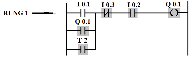
The T2 timer contact
functions as an OR logic in conjunction with Input I0.1 and Q0.1 in the ladder
rung shown above. Once the timer contact output becomes Logic-1, it triggers
the output coil Q0.1, causing it to become Logic-1. The output signal from T2
is a pulse signal since the timer resets itself through the output Q0.3. The
pulse signal is sufficient to activate the output coil Q0.1 and hold it since
the subsequent output functions as a latching circuit. With this modification,
the mixing sequence will run continuously, starting a new cycle every time. An
emergency switch SW2 is included to stop the process at any state.


No comments:
Post a Comment