What is a Logical Function?
A logical function is a
rule-based operation that is executed sequentially in a continuous loop to
perform specific tasks or operations. In the context of programmable logic
controllers (PLCs), logical functions are used to make decisions based on the
results of these functions. For example, an automatic drill machine will only
start when the machine guard is closed. In this case, the machine Start switch
and Guard switch are connected using an AND logic. The drill machine will start
only when both the start and guard switches are activated and in the logic
state 1. There are three basic logical functions: AND, OR, and NOT, and other
logical operations are combinations of these three functions. The following
sections describe different logical functions and their applications in PLC
programming languages.
AND
AND logic is a basic logical function where the output is activated (ON) when two normally open (NO) contacts are simultaneously activated (ON). In the electrical circuit shown below, a lamp will glow only when both switches, Input A and Input B, are triggered simultaneously. If either switch becomes OFF, the lamp will turn off. In PLC programming languages (LAD, STL, and FBD), Input A and Input B switches are represented as input 'I0.1' and 'I0.2' respectively, and the lamp is represented as PLC output 'Q0.0'. The following programming examples demonstrate the AND logical operation in different languages, and the output status is represented by a truth table.

OR
OR logic is another basic logical function where the output is activated (ON) when either of the two normally open (NO) contacts is activated (ON). In the electrical circuit shown below, a lamp will light up if either switch, Input A or Input B, is activated, and both switches should be OFF to turn off the lamp. The switches are connected using an OR logic. In PLC programming languages (LAD, STL, and FBD), Input A and Input B switches are represented as 'I0.1' and 'I0.2' respectively, and the lamp is represented as PLC output 'Q0.0'. All programs express the OR logic using different languages, and the output status is represented by a truth table.

NOT
NOT logic operation triggers
the output (ON) until an Input is deactivated. In the electrical circuit shown
below, a normally closed (NC) contact switch 'Input A' is connected to the
lamp. The lamp turns on when the control is activated (pressed), and the lamp
voltage supply is interrupted when the control is released. In PLC programming
languages (LAD, STL, and FBD), Input A is represented as 'I0.1', and the PLC
output 'Q0.0' represents the lamp output. The programs demonstrate the NOT
logic using different languages, and the output status is represented by a
truth table.

NAND
NAND logic operation
triggers the output when both inputs are deactivated or turned off. In the
electrical circuit shown below, a lamp will glow only if either switch, Input A
or Input B, is deactivated. If both switches are activated, the lamp will turn
off. The switches are connected using NAND logic. In PLC programming languages
(LAD, STL, and FBD), Input A and Input B switches are represented as 'I0.1' and
'I0.2' respectively, and the lamp is represented as PLC output 'Q0.0'. The
programs demonstrate the NAND logical operation using different languages, and
the output status is represented by a truth table.

NOR
NOR logic operation triggers the output when both inputs are deactivated together. In the electrical circuit shown below, the lamp will light up only if both switches, Input A and Input B, are deactivated. If either switch is activated, the lamp will turn off. The switches are connected using NOR logic. In PLC programming languages (LAD, STL, and FBD), Input A and Input B switches are represented as 'I0.1' and 'I0.2' respectively, and the lamp is represented as PLC output 'Q0.0'. The programs demonstrate the NOR logical operation in different languages, and the output status is represented by a truth table.

Exclusive OR
The Exclusive OR (XOR) logic function activates the output when either of the inputs is activated, but both inputs must be activated or deactivated together to trigger the output in the off state. In the electrical circuit shown below, the lamp will light up when either switch, Input A or Input B, is activated. The lamp turns off when both switches are either activated or deactivated together. The switches are treated as "Dual-contact" where one is a normally closed (NC) contact and the other is a normally open (NO) contact for individual control. When a switch is activated, the NC contact opens, and the NO contact makes a connection. The lamp is supplied through any combination of switching contacts when either switch is activated. The electrical diagram represents the deactivated state of the lamp and the activation of both switches, cutting off the electrical supply. The timing diagram shows the output status of the lamp. In PLC programming languages (LAD, STL, and FBD), Input A and Input B switches are represented as 'I0.1' and 'I0.2' respectively, and the lamp is represented as PLC output 'Q0.0'. All programs demonstrate the XOR logic using different languages, and the output status is represented by a truth table.

Exclusive NOR
NOR Exclusive NOR (XNOR) logic operation activates the output when both inputs are activated or deactivated. In the electrical circuit shown below, the lamp will light up when both switches, Input A and Input B, are activated or deactivated together. The lamp turns off when either switch is activated. The switches are also treated as "Dual-contact" with one normally closed (NC) contact and one normally open (NO) contact, but the configuration is different from XOR logic. When a switch is activated, the NC contact opens, and the NO contact makes a connection. The electrical diagram represents the deactivated state of both switches, and the lamp will glow. The electrical supply will lead the lamp through another path when the switches are activated. The switches are connected in XNOR logic, and the timing diagram describes the output status of the lamp. In PLC programming languages (LAD, STL, and FBD), Input A and Input B switches are represented as 'I0.1' and 'I0.2' respectively, and the lamp is represented as PLC output 'Q0.0'. All programs demonstrate the XNOR logic using different languages, and the output status is represented by a truth table.

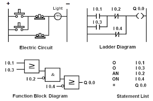
Writing a PLC program using Logical Functions:
We are already familiar with
different types of logical functions associated with PLCs. Here are some simple
examples that illustrate various electrical circuits and their representation
in PLC languages using logical functions. As mentioned earlier, ladder
programming is the simplest way to represent a PLC program, resembling an
electrical wiring diagram.
Example - 1

Example - 2


No comments:
Post a Comment