A feedback element is a precise measuring tool used to measure the linear or angular position, displacement, and sometimes speed in a mechatronics system. These tools continuously send the current position information of a moving object as an electrical signal to the CNC Controller and obtain the actual position and velocity information. Measuring equipment can be categorized into two primary groups: rotary measuring tools (such as Encoder, Resolver, and Tacho generator) and linear measuring tools (such as Linear scale and linear Inductosyn). The function of measuring devices is to generate a constant electronic signal and send it to the Controller. The following are some commonly used measuring devices found in different mechatronics systems.
Optical Encoder:
The optical encoder is the most commonly used rotary-type measuring device in mechatronics systems. It relates the actual position and speed of an element, such as the state of an axis or spindle speed feedback with CNC machines. An encoder is usually integrated inside a servomotor, coupled with the motor shaft, and sometimes separately attached to a ball screw or spindle unit with a timing belt. Inside an optical encoder, a graduated glass disc is attached to a shaft, which rotates freely along with the disc. The glass disc has opaque and transparent portions. Photo-electric cells and light sources are placed on either side of the disc, allowing the light to pass through and strike the photo-electric cells. As the servo motor shaft or ball screw rotates, the encoder shaft, attached to it, also rotates. Due to the transparency and opaqueness of the glass disc, the light emitted from the source sometimes reaches the photo-electric cell and sometimes does not. The output signal from the photo-electric cells is passed through an electronic circuit, where it is converted from a sinusoidal signal to a rectangular waveform, and then transmitted to the Controller via a signal cable. There are two types of optical encoders used with CNC systems: Incremental Rotary Encoder and Absolute Rotary Encoder. The following picture shows an optical encoder widely used with CNC systems.

Incremental rotary encoder -
Incremental measurement refers to computation by counting. The output signal of
an incremental rotary encoder is sent to an electronic counter inside the
Controller. Each increment of the output signal contributes to the
comprehensive measurement. The following picture illustrates how an incremental
rotary encoder works.

The main difference between
an incremental rotary encoder and an absolute rotary encoder lies in the
structure of the graduated glass disk inside the encoder. In the previous
picture, the gratings of the graduated glass disc in an incremental encoder are
marked radially, within a range of 200 PPR (parts per revolution) to 18000 PPR.
The output PPR of an incremental rotary encoder indicates the number of pulses
it will generate with a 360-degree rotation of the Encoder shaft, depending on
these gratings on the glass disc. Here is another grating mark for reference,
which is only marked in one place on the graduated glass disc, indicating the
starting point of the measurement counting.
Absolute Rotary Encoder- The
fundamental working principle of an absolute rotary encoder is similar to that
of an incremental rotary encoder, with the only difference lying in the
construction of the glass disc (refer to the picture below). In an absolute
encoder, multiple tracks are built over a glass disc instead of a single track
as seen in an incremental encoder. Each track consists of transparent and
opaque sections arranged in a specific manner using a different technique. The
composite signals received from the photoelectric cells become unique for a
particular position of the encoder shaft. This means that the combined signals
from the photoelectric cells for different states of the encoder shaft (ranging
from 0 to 360 degrees) also differ sequentially. The unique position of the
encoder shaft is typically defined using binary or Gray code. The image below
illustrates a typical structure of grating marks on a glass disk of an absolute
rotary encoder.

Magnetic Encoder:
Typically, an optical
encoder consists of a glass disc and cannot be used in various mechatronics
systems that involve vibration, extreme heat, or humidity. It is highly
inconvenient to use an optical encoder with a glass disc in such scenarios. On
the other hand, a magnetic encoder performs exceptionally well in harsh and
stressful environments, providing accurate feedback. This type of encoder
utilizes Hall Effect technology, and both rotary and linear magnetic encoders
are compatible with CNC systems.

A magnetic rotary encoder consists of three main components: a magnetic disk, a sensor, and a conditioning circuit. The encoder disk is composed of small magnetic poles arranged in alternating North and South poles along its circumference. As the disk rotates, a sensor inside the Sensing Head converts the magnetic field signal into a Sine wave. The encoder sensor commonly uses a Hall Effect device or, in some cases, a Magneto-resistive element. The signals from the sensor pass through a Conditioning circuit, which converts them into a format understandable to the CNC Controller. The sensor and conditioning circuit are usually integrated inside the sensing head and connected to the controller through a signal cable. The fundamental working principle of a linear magnetic encoder is similar to that of a rotary magnetic encoder, except that a Magnetic tape is used instead of a magnetic disk (refer to the picture), with alternating magnetized poles spread across the tape.
Linear Scale:
A linear scale, also known
as a linear encoder, precisely measures the linear displacement of an object,
such as the linear axis movements of a CNC machine. In CNC machines, a linear
scale is typically installed along the machine slide to provide accurate and
precise position measurements, compared to those obtained from an encoder
usually fixed with a motor shaft. There is always a certain amount of backlash
present when converting linear displacement into rotary movement (like that of
a motor). Therefore, a linear scale offers better accuracy compared to an
encoder.

A linear scale consists of two separate units: a glass scale and a reading head. One of these units, either the glass scale or the reading head, is attached to the moving body, while the other remains stationary. The glass scale is similar to an encoder's glass scale and is fabricated with alternating transparent and opaque gratings. The reading head contains a light source, lens, scanning reticle, and photo-electric cells, similar to an encoder. When the reading head moves over the glass scale, the transparent and opaque grating parts align with the scanning reticle index alternately. This causes the light passing through the lens to reach the scanning reticle and glass scale, eventually falling on the photo-electric cells. As a result, the photo-electric cells generate a sinusoidal signal based on the fluctuations of light. The sinusoidal signal is then converted to a rectangular waveform using an electronic circuit within the reading head and sent to the controller via a flexible cable.
Resolver:
A resolver is a rotary measuring device that provides position and velocity feedback of a rotating device. It consists of a motor shaft and is used to obtain information about the rotating device's position and velocity. The resolver is composed of two stator windings and a rotor winding. The stator windings are wrapped in such a way that there is a 90° phase shift between them. The rotor and stator windings function as primary and secondary windings of a transformer and are assembled inside the resolver. When a sinusoidal signal passes through the stator windings with a 90-degree phase shift, a sinusoidal signal is induced in the rotor winding. As the rotor shaft rotates, the output signal changes in accordance with the reference signal, and the magnitude of the output signal depends on the rotation of the resolver shaft. The output signal phase changes from 0° to 360° as the resolver shaft rotates continuously. Since controllers only recognize digital information, the resolver's output signal is converted into a digital signal before being sent to the controller. The following image shows a resolver commonly used in CNC systems.

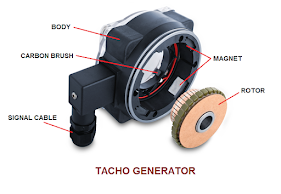
Tachogenerator:
A tachogenerator is a rotary
measuring device used to obtain speed feedback from a rotating element. It was
commonly found in earlier mechatronics systems, but nowadays, optical encoders
transmit both speed and positional feedback, making the use of tachogenerators
almost obsolete. A tachogenerator is a simple permanent magnet DC generator
typically installed with a servomotor or a rotating object shaft. It produces a
DC voltage that serves as the signal output. The analog DC voltage generated by
the tachogenerator changes with the motor's RPM, and the controller receives
this information by measuring the analog voltage, and determining the speed or RPM
of the motor. The following picture shows a simple DC tachogenerator.
Inductosyn:
Inductosyn is a type of
analog precision measuring equipment and is considered one of the most accurate
position-measuring devices in the world. There are two main types of
Inductosyn: linear and rotary. The linear type consists of a scale and a
slider, while the rotary type includes a rotor and a stator. Inductosyn is
commonly used for high-accuracy measurements and operates effectively in harsh
environments. One advantage of using a linear Inductosyn over a linear scale is
that the scale is easily expandable and suitable for measuring over long
distances.
The operating principle of
an Inductosyn is similar to that of a multi-pole wire-wound resolver. In a
rotary Inductosyn, the rotor and stator have printed circuit patterns that
function as two windings in a rotating transformer. An AC signal is applied to the
rotor winding, inducing a current in the stator winding as the rotor rotates
relative to the stator. The output amplitude varies in a cyclic sinusoidal
pattern, providing a signal output. This output signal is then amplified and
transmitted to an Analog-to-Digital converter circuit to obtain a reliable
output signal for the controller.

A linear Inductosyn can be
thought of as a resolver that has been unwound on a flat surface. In this case,
the scale of a resolver is represented by the Inductosyn scale, which is
typically placed on a machine bed, while the rotor of a resolver is equivalent
to the slider of a linear Inductosyn. The slider moves over the scale,
maintaining a small gap (usually 200 microns). Similar to a resolver, the
slider in an Inductosyn also contains two windings. A sinusoidal voltage is
applied to these windings with a 90-degree phase difference, and the induced
voltage in the windings is considered as the signal output. The induced voltage
is usually low (microvolts), so an appropriate pre-amplifier is always used
with Inductosyn to amplify the voltage, enabling direct interfacing with the
controller.


No comments:
Post a Comment