Electric Actuators:
An electric actuator is a device that utilizes an electric motor to generate the necessary force for creating movement in machinery or performing actions such as clamping. In CNC machines, electrically operated actuators are integrated with various mechanisms. The following is a brief list of actuators commonly used with CNC machines:
a) AC and DC motorsb) Servo motors
c) Stepper motors
d) Electric Linear Actuators (ELA)
e) Solenoid valve coils
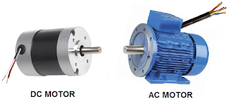
AC and DC motors - Electric motors are electromechanical devices that convert electrical energy into mechanical energy. AC or DC motors are used in mechatronics systems based on the specific requirements of the system. AC motors are generally preferred over DC motors due to the absence of a commutation process and the absence of carbon brushes. AC motors are available in single-phase or three-phase configurations, whereas DC motors are typically single-phase. Three-phase AC motors are self-starting, while single-phase AC motors require a starting torque. DC motors are also self-starting. However, despite their limitations, DC motors are still used in small applications because they provide higher starting torque compared to AC motors. Designing small AC motors is impractical. CNC machines and mechatronic systems commonly utilize three-phase induction motors. The following pictures show a DC motor and an AC three-phase induction motor.
Servo motors - Servo motors are electromechanical devices primarily used to drive the axes and spindles of CNC machines. These motors offer higher torque with lower current consumption compared to conventional motors, making them more compact and efficient. Both DC and AC (brushless) servo motors are used and are sometimes referred to as control motors, as they control the mechanical transmission system. Servo motors always operate within a closed-loop servo system. In the past, CNC machines used both types of servo motors, but AC servo motors offer several advantages over DC servo motors. As a result, most CNC machines now exclusively use AC servo motors for spindle and axis movement. The following picture shows different AC servo motors.

Stepper motors - Stepper motors are brushless synchronous motors that accurately control the speed by dividing the 360-degree shaft movement into multiple steps. The motor shaft moves one step with each electrical pulse, which gives these motors their name. Stepper motors typically work with a driver unit that generates electrical pulses to rotate the motor shaft. The speed of a stepper motor depends on the frequency of the electrical pulses. The following picture shows a stepper motor and its internal components.

Electric Linear Actuators
(ELA) - Electric linear actuators usually incorporate a 12V DC motor (sometimes
with different ratings) and utilize a lead screw and nut system with a gear
assembly. Rotating the lead screw produces linear movement in a shaft attached
to the nut assembly. Electric linear actuators offer several advantages over
hydraulic or pneumatic linear actuators. They have a compact design and do not
require valves, pumps, pressure lines, etc., to achieve linear movement. The
following picture shows an electric linear actuator.

ELAs perform various
functions in mechatronic systems, and the stroke measurement of an ELA depends
on the length of the lead screw. Clockwise and anticlockwise movements of the
motor shaft cause the shaft of an ELA to extend or retract. Once it reaches
both ends, the motor supply is terminated through small snap switches usually
located inside the ELA.
Solenoid valve coils - Solenoid valve coils are electromagnetic actuators that control hydraulic or pneumatic pressure lines by utilizing electrical power. These coils are typically made of insulated copper wire wrapped around a hollow cylinder, which generates a magnetic field when an electrical current passes through the coil. The coil is attached to a solenoid valve (hydraulic or pneumatic) in a way that ensures proper alignment with a ferromagnetic core inside the valve, known as the valve plunger. When a magnetic field is created inside the hollow cylinder, the valve plunger becomes an electromagnet and attempts to move outward from the coil. As the plunger moves, it opens an orifice inside the valve, thereby influencing the pressure line in a specific direction. The following pictures show the energized and de-energized states of a pneumatic solenoid valve, with the movement of the magnetic plunger directing the opening and closing of an air pressure line. Solenoid valve coils are available in both DC and AC voltage types, commonly used voltages being 24V DC and 110/220/240V AC for CNC machines and various mechatronic systems. Different energy sources are used for solenoid coils in hydraulic and pneumatic valves. Typically, 24V DC coils are used with pneumatic valves, while 110/220V AC coils are used with hydraulic valves. The following picture shows a 24V DC pneumatic solenoid valve in both energized and de-energized states.

Hydraulic Operated Actuator:
Hydraulic actuators convert
pressurized hydraulic fluid energy into mechanical motion. In a hydraulic
system, a hydraulic pump, driven by an induction motor, generates pressurized
hydraulic fluid. This fluid passes through several valves and operates
different hydraulic actuators. Hydraulic pressure is used for mechanical
functions such as blocking, clamping, and ejecting, and sometimes for power
transmissions. In mechatronics systems, multiple tasks are executed through
various hydraulically operated actuators. The functioning of a hydraulic
actuator depends on factors such as hydraulic fluid pressure, flow rate, and
pressure drop within the actuator. Hydraulic actuators are commonly divided
into two basic types: linear actuators and rotary actuators. Linear actuators
include different cylinders, while the hydro-motor functions as a rotary
actuator.
Linear Hydraulic Actuator: A
linear actuator is employed to transfer or displace an element in a straight
line, and the displacement is determined by the stroke length of the actuator.
The most commonly used linear actuator in machinery is the hydraulic cylinder,
which is usually made of steel to withstand powerful hydraulic pressure
operations. The movement of the cylinder is driven by a piston rod inside the
hydraulic cylinder, exerting force through pressurized fluid. The piston rod is
connected to the external load and generates a pull or push force in a straight
line. Hydraulic cylinders are mainly classified into two types: single-acting
and double-acting cylinders.
Single-Acting Cylinder: Inside a single-acting cylinder, a piston is placed within a cylindrical housing, also known as a barrel. A solid rod is attached to the piston, allowing it to move forward and backward with the piston. To prevent the pressurized fluid from penetrating the upper part of the cylinder, a rubberized piston seal is positioned adjacent to the diameter of the piston. The cylindrical housing contains a pressure port through which pressurized fluid can enter or exit the cylinder. The cylinder's piston is driven in one direction only by pressurized fluid, and spring tension is applied to return the piston to its original position.

A small port called a vent port is present opposite the pressure port and is used to ventilate the air accumulated inside the upper or lower part of the cylinder to the atmosphere. The control valve regulates the incoming pressure line, pushing the cylinder piston outward, sending back the fluid to the tank, and retracting the piston's action. The hydraulic fluid accumulated in the lower or upper part of the cylinder piston returns to the hydraulic tank through the control valve. Single-acting cylinders can be classified into two varieties: push-type and pull-type. The fundamental operation of these two cylinders is the same, with the only difference being the position of the pressure port and vent port, which are positioned in the opposite direction.

Double-Acting Cylinder: The
operation of a double-acting cylinder is similar to that of a single-acting
cylinder. However, instead of a spring action, an extra pressure line is
provided for the reverse movement of the cylinder piston. A double-acting
cylinder has two separate pressure ports at the top and bottom ends, enabling
the piston to actuate in both directions.

With double-acting cylinders, a piston rod can be on either side of the cylinder or on both sides. In most cases, a double-acting cylinder with a one-sided piston rod is used in mechatronics systems, while both-sided piston rod cylinders are found in some cases. Double-acting hydraulic cylinders are commonly used for linear movement in various mechanisms.

Rotary Hydraulic Actuator: In mechatronics systems and CNC machines, hydraulic rotary actuators are preferable over induction motors due to their ability to provide high torque and handle heavy-duty rotary motion. Hydraulic actuators are more efficient when it comes to indexing heavy loads or performing shifting and rotating tasks. There are two types of hydraulic rotary actuators: limited movement and continuous movement. Limited movement hydraulic rotary actuators are also known as hydro-motors. Different types of limited movement rotary actuators are available based on their movement type and work form, including rack & pinion type, crank lever type, vane type, parallel piston type, etc. The images below illustrate a rack & pinion type and a vane type limited movement hydraulic rotary actuator, commonly used in various mechatronics systems.

For heavy-duty applications
requiring slow and continuous rotary motion, a continuous movement hydraulic
rotary actuator or hydro-motor is typically employed. Machines that need to
rotate heavy loads with a slow and steady movement often utilize a hydro-motor
instead of an induction motor. Despite performing the same tasks, hydro-motors
are generally smaller in size compared to induction motors. Various types of
hydro-motors are available, including gear type, piston type, vane type, etc.
The image below shows a vane-type hydro-motor commonly found in mechatronics
systems and CNC machines.

Pneumatic Operated Actuator:
A pneumatic actuator converts the energy of compressed air into mechanical
motion. When gaseous elements like air are compressed, their volume decreases,
resulting in an increase in pressure. This enhanced pressure can be utilized to
perform various mechanical work. Compressed air is accumulated in a reservoir
for later use. Pneumatic actuators are used for tasks such as automatic machine
door opening and closing, and changing the arm movement of a cutting tool.
Since pneumatic pressure is typically maintained between 5 to 7 kg, pneumatic
actuators are suitable for overcoming light loads. For larger burdens, a
large-diameter cylinder piston is required. Pneumatic cylinder bodies are
usually made of aluminum or its alloy, making them lighter compared to
hydraulic cylinders. Pneumatic actuators, like hydraulic actuators, can be
classified into linear and rotary types.
Pneumatic Linear Actuator: Pneumatic linear actuators refer to a range of pneumatic cylinders. Pneumatic cylinders come in different types depending on their structure and operation. Due to the lower compressed air pressure compared to hydraulic pressure, the mechanical thrust or power available with a pneumatic cylinder is also lower. Therefore, the structure of a pneumatic cylinder is always lighter compared to a hydraulic cylinder. If the same amount of work is performed with a pneumatic cylinder instead of a hydraulic one, the barrel diameter of a pneumatic cylinder will be larger. Pneumatic cylinders are more convenient to use in mechatronics systems. However, for steady force and fluctuating loads, a hydraulic cylinder is generally preferable.

Pneumatic cylinders have an
instantaneous response time but also come with some disadvantages. When the
cylinder completes its stroke, the piston thrusts extensively at the end
covers, which can damage the cylinder. To overcome this problem, every
pneumatic cylinder includes a cushioning system that reduces the piston
movement when it strikes the cylinder edge. Pneumatic cylinders have two types
of cushioning systems: fixed type and adjustable type. The fixed cushioning
system is preferred for lower diameter pneumatic cylinders, while the adjustable
system is used when the cylinder piston speed is relatively high. Different
types of cylinders are selected based on the requirements of different
mechatronics systems, including single-acting, double-acting, and rodless
pneumatic cylinders.
Single-Acting Pneumatic Cylinder: The functioning of a single-acting pneumatic cylinder is similar to that of a single-acting hydraulic cylinder. It consists of a piston placed inside a cylindrical barrel, with a rod attached to it that moves with the piston. The cylinder's piston displacement is achieved by air pressure and retracted by the compression or expansion of spring tension. These cylinders also have fixed or adjustable cushioning systems. Like hydraulic cylinders, single-acting pneumatic cylinders are available in two varieties: push-type and pull-type.

Double-Acting Pneumatic
Cylinder: Double-acting pneumatic cylinders operate similarly to hydraulic
cylinders. They can be divided into two types: piston rod on one side and
piston rod on both sides. Both types of cylinders have a cushioning system.

Rodless Pneumatic Cylinder: Rodless pneumatic cylinders have a different function compared to fundamental cylinders. These cylinders do not have a piston rod connected inside the cylinder piston. Instead, the piston is coupled with an outer load-carrying cartridge through magnetic or mechanical coupling. Rodless pneumatic cylinders come in three types: cable cylinder, sealing band cylinder with slotted cylinder barrel, and magnetically coupled slide cylinder. Among these types, sealing band and magnetically coupled cylinders are commonly used in mechatronics systems.

Pneumatic Rotary Actuator: A pneumatic rotary actuator conveys rotary movement using pneumatic energy or air pressure. There are two types of pneumatic rotary actuators: continuous rotary movement and limited rotary movement. The continuous rotary motion pneumatic actuator is sometimes referred to as a pneumatic motor. This motor delivers a constant rotary motion by utilizing a pneumatic pressure line. Based on their structure and working principle, pneumatic motors can be classified into three types: piston motor, sliding vane motor, and gear motor. The image below depicts a sliding vane pneumatic motor.

A limited movement pneumatic
rotary actuator allows for higher torque. The standard rotation angles for
these actuators are usually 90°, 180°, and 270°. There are three different
types of pneumatic rotary actuators available in the market: vane type, rack &
pinion type, and helix spine type. The images below display a rack & pinion
type limited movement rotary actuator.


No comments:
Post a Comment