Preparatory Function
The preparatory functions
define the dimensioning of the workpiece, interpolation movements, the
operating state of a machine, and the selection of work offset, among other
things. These functions are executed within a program specified with different
G-Codes. For example, G01 expresses linear interpolation, and G02 defines
circular interpolation in a clockwise direction. The G-Codes are usually
categorized into separate groups, typically for all types of CNC controllers.
Within a program block, only one G-Code can be used from a particular group.
However, many G-Codes from different groups can be used within the same program
block.
Miscellaneous Function
Various operations with CNC
machines, such as coolant on/off, automatic tool and palette changing, and other
functions, are carried out by applying M-Codes. M-Codes are commonly defined by
machine builders and may vary depending on the machine type. Some common
M-Codes include M03, which is used to rotate the spindle clockwise, and M06,
which is used for tool changing. These M-Codes perform miscellaneous functions
when operating with CNC machines.
Interpolation
Interpolation movement in
CNC machine programming allows for the combined motion of two axes from one
point in two different ways: a straight path or a circular path. When the axes
move in a straight line, it is called linear interpolation, while a rounded
path is referred to as circular interpolation. The G01 code is used in a
program to define linear interpolation movement, while the G02 code represents
circular interpolation in a clockwise direction. Circular interpolation in an
anticlockwise direction is achieved with the G03 code. Circular interpolation
programs with G-Codes can be written in two different ways: specifying the
arc's starting point and endpoint along with the arc radius, or specifying the
starting point and endpoint along with the location of the arc's center point.
The pictures below depict linear interpolation and circular interpolation
movements between points P (05, 05) and Q (10, 10).

Cutter Radius Compensation or CRC
During a machining operation, when an end-mill cutter positions itself, its center point aligns with the programmed endpoint. However, it is necessary to shift the cutter's center towards the left or right direction to align the cutter edges with the programming line. Cutter Radius Compensation or CRC is a function where a CNC controller automatically adjusts the centerline of a cutting tool to deviate from the actual programming path. This ensures that the cutting tool's edges align with the programming path (see picture below). Cutter radius compensation is commonly applied in continuous path milling operations. In programming, CRC is activated in the right direction using the G42 code and in the left direction using the G41 code. When G41 is used in a program, the cutter engaged in machining automatically shifts its centerline to the left direction, ensuring that the cutting edges touch the actual programming path. Similarly, the G42 command deviates the cutter's centerline towards the right, and the G40 code cancels the CRC activation. The picture below illustrates how cutter radius compensation works, where the G41 code is used to shift the cutter's centerline to the left direction.

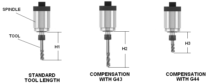
Tool length compensation
Tool length compensation is
the process of adjusting for the difference in length between an actual tool
and a standard tool assumed during programming. Different tools with varying
measurements are used for different machining operations. By using CNC programming,
tool length compensation ensures that the axis movement accurately corresponds
to the cutting tool's position. If the actual tool length is longer than the
standard tool, the G43 code is used to compensate for it, while the G44 code is
used for shorter tool lengths. The G49 code cancels the compensation value
before proceeding with subsequent machining operations. The following picture
illustrates the concept of tool length compensation.
Tool radius compensation
In CNC turning machines, the
tool tip is always slightly rounded, and programming considers a theoretical
tool nose point. Consequently, when taper cutting or performing arc
interpolation movement between the programmed path and the actual cutting path,
a rounding shape appears. Tool radius compensation automatically eliminates
this problem by calculating the error and compensating for the tool nose radius
value. When programming, the G41 code is used for left mode tool radius
compensation, while the G42 code is used for right mode. The G40 code cancels
the tool radius compensation. The following pictures illustrate the procedure
for tool radius compensation during turning operations.

Canned cycle
Canned cycles are
pre-programmed machining processes such as drilling, boring, and tapering that
are permanently stored in the CNC controller's memory. These cycles utilize
special codes that act as macro programs, making programming simpler. For
instance, a peck drill cycle program can complete a hole using just two lines
of code, whereas writing the same program separately would require more than
twenty lines. Canned cycle programs employ specific codes and adjustable
parameters to accommodate different lengths and diameters of machining
operations. CNC system builders typically provide canned cycle programs that
are stored in the controller's memory, allowing users to modify certain
parameters to achieve the desired outcome. Peck drilling, tapping, and boring
are examples of common canned cycles frequently used in CNC machining for
efficient programming.
Selection of Plane
Plane selection is crucial when programming circular interpolation movements. Circular interpolation involves the simultaneous movement of two axes, and the axes to be driven are selected using G-codes. The G17, G18, and G19 codes activate the selection of the XY, XZ, and YZ planes, respectively. By utilizing these codes in programming, the controller identifies which plane will be used during a machining operation. The following pictures depict the selection of planes for milling and turning operations.

Typically, the XZ plane or G18 is used for turning operations, where only the X and Z axes are involved in the simple turning process. For milling operations, three planes may be used (as shown in the earlier picture). If no plane is selected during programming, the turning program assumes the XZ plane by default, and the XY plane for milling operations. The following pictures demonstrate the cutter movements during circular interpolation movements with different planes on a vertical milling machine. The G02 and G03 codes represent the cutter movements for clockwise and counterclockwise directions, respectively.


No comments:
Post a Comment