Water level controller
Set-Reset functions with ladder logic are represented in this simple example. The purpose is to demonstrate how a Programmable Logic Controller (PLC) can automatically control the water flow entering and exiting a water tank, maintaining a specific water level. The system consists of two solenoid valves, S1 and S2, connected to the water lines, which control the inlet and outlet flow respectively. Additionally, two float switches, F1 and F2, are installed at the top and bottom of the tank to indicate the upper and lower water levels.
When the upper-level float
switch, F1, is activated, it sends a 'Water level high' signal to the PLC.
Conversely, the lower-level float switch, F2, addresses a 'Water level low'
signal. The circuit is operated using push switches SW1 and SW2, which turn the
entire system on and off. To initiate the process, the start button is pressed,
causing the inlet valve to open and water to enter the tank. Once the water
reaches a certain level inside the tank, the upper-level float switch, F1, is
activated, resulting in the closure of the inlet valve to prevent further water
from entering. Simultaneously, the outlet valve opens automatically, allowing
water to drain out of the tank. This process continues until the water level
inside the tank reaches its lower limit and activates the lower-level float
switch, F2.
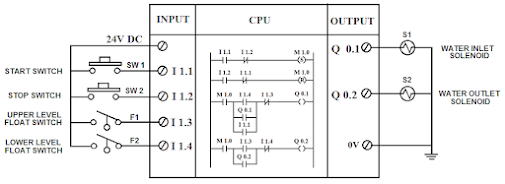
Upon receiving the signal from F2, the output valve closes, and the water inlet solenoid, S1, opens automatically, allowing water to enter the tank again. This process continues until the stop switch is pressed, disabling the entire system. The complete process is explained in the schematic diagram below.
Input
and Output Elements and Their Addresses in the Ladder Diagram
Input elements
- Start switch (SW1) = I1.1
- Stop switch (SW2) = I1.2
- Upper-level Float witch (F1) = I1.3
- Lower level Float switch (F2) = I1.4
Output elements
- Water Inlet Solenoid valve (S1) = Q0.1
- Water Outlet Solenoid valve (S2) = Q0.2
Interfacing of elements with PLC
The following picture depicts the hardware configuration and interfacing of various Input and Output elements with the PLC.
Ladder diagram
Below
is a comprehensive Ladder diagram, consisting of four separate rungs, each
presented independently.
In this rung, M1.0 is an "Internal Relay," also known as a "Flag" for SIEMENS make PLC. It is activated using the SET logical function. PLC operates with Retentive and Non-Retentive type Flags. M1.0 is a Non-Retentive type Flag, and its status becomes Logic-0 when the power supply to the PLC is turned off. The status of Flag M1.0 is verified as Logic-1 using inputs I1.1 and I1.2, which are implemented here as NO and NC Contacts with AND Logic. Pressing the start switch SW1 sets the M1.0 Flag to Logic-1, as SW2 is an NC Contact. The status of M1.0 remains Logic-1 even after releasing the switch SW1.
Rung – 2
The "RESET" logic is implemented for Flag M1.0 in this rung. Inputs I1.1 and I1.2 are used as NC and NO Contacts, respectively, performing an AND operation to reset the Flag. When the Stop switch SW2 is pressed, the status of M1.0 becomes Logic-0. If the Flag's status is already Logic-0, it remains unchanged.
Rung – 3
Let's consider the water tank is initially empty, so the input status of I1.3 is Logic-0 and I1.4 is Logic-1. Pressing the switch SW1 sets M1.0 to Logic-1, and Q0.1 becomes High. M1.0, I1.1, and I1.3 (NC contact) work together with AND logic in this case. Releasing the switch SW1 keeps the output Q0.1 ON, as it acts as an NO Contact through OR Logic with I1.1 and I1.4, creating a latching circuit. Once Q0.1 becomes high or Logic-1, it energizes the water inlet solenoid S1, allowing water to enter the tank. This process continues until the accumulated water level triggers the upper-level float switch F1, causing Input I1.3 to become Logic-1. Once I1.3 becomes high, Q0.1 turns Logic-0 (since I1.3 is used here as NC logic), and solenoid S1 de-energizes, stopping the water from entering the tank.
Rung – 4
As water enters the tank,
after some time, the Input I1.4 of the lower-level float switch F2 becomes
Logic-0 and stays that way as the water level continues to rise. When the
rising water level activates the float switch F1, I1.3 becomes Logic-1, causing
Output Q0.2 to become Logic-1 and energizing the water outlet solenoid coil S2.
In this case, Flag M1.0, I1.3, and I1.4 (NC contact) work together with AND
logic. Water starts flowing out of the tank through the valve by energizing
solenoid S2. As water flows out, after a while, F1 gets deactivated, changing
its status to Logic-0, and the output Q0.2 remains activated. Q0.2 functions as
a Contact, operating OR logic with Input I1.3, creating a latching circuit.
This state continues until the lower-level float switch F2 is activated. Water
stops flowing outward, and Output Q0.2 becomes Logic-0 as Input I1.4 becomes
Logic-1. The program then follows the sequence described in Rung-3, as this
state satisfies activating Q0.1, continuing the cycle. To stop the cycle or
sequence of operation (automatic water inlet and outlet) at any point, pressing
SW2 sets M1.0 to Logic-0 and de-energizes either solenoid valves S1 or S2. If
we pause the cycle temporarily and the water level is between the upper and
lower levels, pressing the SW1 switch will always turn the S1 solenoid ON.


No comments:
Post a Comment