In a CNC machine, several
mechanical elements such as the machine structure, guideways, and bearings
function with different activities, making it highly reliable. Among them, the
following elements are commonly found in different types of CNC machines:
Machine Structure:
The machine structure serves
as a fully supportive member capable of carrying the load on the machine. All
the motor drive mechanisms and other functional devices operated with CNC
machines are closely associated with the machine structure. During the machine's
running time, two different types of forces or loads are continuously engaged
with the machine structure: static and dynamic loads. The machine structure is
always selected in a way that it does not disrupt the geometric accuracy with
the magnitude and direction of the applied static and dynamic forces. It is
also important to ensure that the machine structure does not vibrate or deform
during machining operations.
Static loads of CNC
machines: Static loads on a CNC machine consider the combined weight of machine
slides with the workpiece, the collective load of functional devices attached
to the machine body, and the forces employed during machining operations. To
overcome the cumulative static loads without causing deformation on the machine
structure, a CNC machine requires a rigid and properly structured
configuration. Most CNC machining centers are constructed with two separate
arrangements: the moving column type and the fixed column type structure. The
following pictures show two different structural versions commonly found in CNC
machining centers.

Dynamic loads of CNC machines: Dynamic loads on a machine structure are continuous and irregular forces that develop due to several moving elements. These variable forces originate from unbalanced rotating devices such as motors, improper gear matching, irregular bearing rotation, and interrupted cutting during machining operations. It is essential to ensure that dynamic loads do not cause severe vibrations or distortions in the machine structure.
Guideways:
Guideways are
effectively applied to support and sustain different static and dynamic loads
in a machine while reducing friction and thrust during axis movement. Guideways
are typically categorized into two types based on their nature and
construction: friction guideways and anti-friction linear motion guideways.
Guideway selection is usually based on load-carrying capacity, damping
properties, and axis traverse speed. Additionally, some special-purpose
machines use hydrostatic guideways and aerostatic guideways, but their usage is
limited. The following are commonly used guideways in CNC machines:
Friction guideways: Friction guideways, cheaper and with superior damping properties, are typically used with conventional machines. Some earlier and less expensive CNC machines also utilize them. A typical anti-friction material such as PTFE or TURCITE is used between two moving parts to reduce friction force between moving and sliding surfaces. Friction guideways are commonly used in three different configurations: VEE, FLAT, and DOVETAIL. The following pictures illustrate different types of friction guideways and demonstrate the installation of anti-friction materials (PTFE or TURCITE) to reduce friction force.

Anti-friction linear motion
guideways: To overcome the higher friction power between a rigid surface and a
sliding body, CNC machines commonly use anti-friction linear motion guideways.
These guideways require less motor power for machine axis movement, resulting
in smoother and easier operation. They also reduce deterioration between
sliding and fixed body surfaces. CNC machine manufacturers commonly employ
three types of anti-friction linear motion guideways:
- Recirculating ball bushing
- Linear bearings with balls and rollers
- Recirculating roller bearing pad
Recirculating ball bushing:
This system utilizes precision balls embedded inside a cartridge that
recirculate through a return path to carry the load. Two types of recirculating
ball bushing systems are typically used: open and closed. This system exhibits
minimal friction and does not necessarily have a clearance like sliding-type
guideways, but proper clearance is maintained for lubrication during axis
movement. The following pictures depict two types of recirculating ball bushing
systems.

Linear bearings with balls and rollers: Linear bearings with balls and rollers operate on the principle of rolling motion, which is more convenient than sliding motion. Recirculating balls rotate over the guideways rail, with the balls only contacting the guideways inside a cartridge. A pair of guideways rail attached to the machine casting body ensures strong and smooth axes movement with minimal friction. The balls used in this system allow rolling motion and only have a line of contact with the guideways rail, resulting in low friction. A pair of linear bearings is used on a machine. The following pictures show a pair of linear bearings with balls and rollers and their usage area in a CNC machine.

Recirculating roller bearing pad: These bearing pads are also found in CNC machine guideways. They consist of recirculating rollers rotating inside a sealed block and fitted separately as pads to carry the load. These pads roll over strong guideways made of steel and can handle heavy weights. A pair of roller bearing pads is always used collectively with guideways, significantly reducing frictional force under heavy loading. The following picture shows a pair of recirculating roller-bearing pads.

Hydrostatic guideways: Some special-purpose CNC machines utilize hydrostatic guideways, where a thin layer of hydraulic oil is seated between static and moving surfaces at very high pressure (about 300 bar). A chamber system carriage is charged with hydraulic oil, which is continuously pressurized, and the unpressured oil is extracted from the compact guidance system on the extraction site and fed back to the oil tank. This system effectively eliminates frictional force. However, the usage of these guideways is limited due to higher costs and the inconvenience of fitting this system into a machine. The following picture shows typical hydrostatic guideways.

Aerostatic guideways: In an
Aerostatic Guideways system, the moving slide is slightly floated over the
static surface using compressed air, creating an air cushion that separates the
guideways or stationary surfaces from the movable slide. Although there is
almost no frictional force between the two surfaces, this system reduces the
load-carrying capacity of the machine. Aerostatic guideways are commonly not
used in CNC machines and are primarily found in Coordinate Measuring Machines
(CMMs) or similar measuring instruments.

Bearings:
A bearing is a
mechanical component that restricts relative movement to the desired motion and
reduces frictional resistance. It is used to facilitate rotary or linear
movement while carrying a load and allowing movement between an axis or
spindle. There are various types of bearings available in the market for
different purposes. Rolling contact bearings, which use spherical balls or
other rolling elements, are widely used in CNC machines to enable transmission
between stationary and moving components.
Rolling Contact Bearings: A
rolling contact bearing, also known as an anti-friction bearing, minimizes
friction between rotating and stationary surfaces. It is typically constructed
with rigid rolling elements such as balls or rollers and races. The race
provides support for the rolling components during rotation. With anti-friction
bearings, there is minimal friction between the rolling elements and the race,
requiring only a small amount of lubrication for smooth rotation. These
bearings are commonly used in CNC machines, including spindle and axis ball
screw rotations, which operate at high speeds with a high load-carrying
capacity.
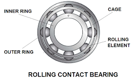
Elements of Rolling Contact Bearings: Rolling contact bearings consist of inner and outer rings, rolling elements, and a cage. The inner and outer rings guide the rolling elements, allowing them to rotate freely between them. They transmit axial loads applied to the bearing in the direction of rotation. The rolling elements can be of different shapes, such as balls or rollers, and various types, including cylindrical roller, needle roller, tapered roller, symmetrical barrel roller, asymmetrical barrel roller, etc. The cage plays a significant role in the bearing by maintaining a uniform gap between the rolling elements to prevent collisions and ensure the load applied to the bearing is distributed evenly. Different types of cages, such as metallic or non-metallic, are used with rolling contact bearings. The picture below illustrates a rolling contact bearing and its internal parts.
Types of Rolling Contact Bearings: There are two main types of rolling contact bearings used in CNC machines based on the applied load: radial bearings and thrust bearings. Thrust bearings typically have a larger load-carrying capacity compared to radial bearings. The nominal contact angle of a radial bearing usually ranges from 0 to 45 degrees, while for a thrust bearing, it is between 45 and 90 degrees. The term "nominal" contact angle refers to the angular value between the rolling element and the radial plane. The picture below shows the two types of bearings.

Rolling contact bearings are further categorized into two groups based on the rolling elements: ball bearings and roller bearings. Ball bearings can be classified as Deep Groove or Angular Contact bearings. Roller bearings, on the other hand, have three different types based on the construction of the rollers: cylindrical roller, needle roller, and tapered roller. The picture below illustrates different types of bearings.

Ball Screw Support Bearings: Ball screw support bearings are used on both ends of a ball screw to rigidly hold it with the machine body. They can be assembled in pairs, triplets, or more to enhance the loading capacity of the ball screw. The internal configuration of ball screw support bearings provides higher rigidity, minimal axial run-out, high running speed, and a longer lifespan. These bearings help the ball screw achieve optimal accuracy. The picture below shows a pair of ball screw support bearings and how they are fitted with a ball screw.

Assembly of Bearings with CNC Machine Spindle: Typically, a pair of bearings are positioned together in three different ways with the spindle assembly: face-to-face, back-to-back, and in tandem. The back-to-back arrangement is the most commonly used bearing assembly in CNC machine spindles. It offers greater accuracy and higher rigidity compared to other arrangements. The face-to-face bearing assembly is rarely used with CNC machine spindles and is sometimes found in tandem assembly. Since tandem mounting cannot withstand both axial and radial loads on a spindle, two additional bearings are applied to the spindle housing to overcome this limitation. The picture below shows two different loadings applied and the three types of bearing mountings.

Pre-loading of Bearings: Different bearing assemblies always have some axial and radial clearances. These clearances can cause inaccuracies in spindle rotation and axis movement when the bearing is assembled with a spindle or axis ball screw. To minimize or eliminate these clearances, pre-loading is required. In this system, external thrust is initially applied to the bearing, which eliminates the axial and radial play that follows. Pre-loading is necessary for bidirectional movement without any backlash. The picture below illustrates a double-nut pre-loading system where a plate or spacer is placed between two nuts. The nuts are tightened with a tension load greater than the maximum operating load. As a result, the bearing balls on one side exert pressure on one edge of the ball screw thread, while the balls on the other side press the opposite edge of the ball screw.


No comments:
Post a Comment