A mechanical power
transmission is a fundamental mechanism used to automate various tasks by
employing multiple actuator movements. Examples include driving a motor and its
pairing mechanism, enabling axis movement, or controlling the motion of a
robotic arm in different directions. These power transmissions are crucial
components in complex mechatronic systems and CNC machines. Some systems
convert rotary motion into linear movements, such as the ball-screw and nut
system, while others are designed for torque transmissions, like gearboxes, timing
belts, and couplings. Worm and worm shafts are commonly used to transmit rotary
motion between different planes, and various index mechanisms are employed in
mechanical power transmissions. The following mechanical power transmission
systems are typically utilized in CNC machines and mechatronic systems.
Spindle Headstock :
The spindle headstock is a complete arrangement for transmitting power between the spindle and the drive motor unit. In some cases, it also includes a tool clamp/unclamp mechanism. For CNC machining centers, the spindle headstock is commonly associated with the vertical axis, while in turning centers, it remains stationary. A typical spindle headstock consists of the following components:
a) Spindle drive motorb) Spindle
c) Gear-shifting mechanism
d) Power draw bolt for the tool clamp/unclamp mechanism
e) Spindle orientation mechanism

a) Spindle drive motor: This servo motor operates the spindle in CNC machines, and its rating depends on the required torque for spindle handling. CNC machines use high-power servo motors with a wide speed range to drive the spindle. In some cases, two or three-step gearboxes are also used in conjunction with the spindle motor to achieve the desired spindle speed. However, most CNC machines directly drive the spindle using a spindle motor connected via a timing belt, rather than a gearbox. Some CNC machines utilize an integral spindle motor, which simulates the spindle and delivers the necessary torque without the need for a gearbox or timing belt.
b) Spindle: The spindle is responsible for holding the cutting tools that remove material from the workpiece during machining. It requires a single or multipoint cutting tool with different rotational speeds, typically ranging from 30 to 6000 rpm or higher. During machining, the spindle experiences torsional and radial deflections and undergoes thrust forces based on the machining operations. Therefore, the spindle structure is designed to withstand these deflections and loads. A typical spindle consists of three main components: the spindle housing, spindle nose, and bearings. The spindle nose is securely fitted inside the spindle housing with bearings, allowing it to rotate freely without friction. Different types of tool holders with cutting tools can be securely attached to the tapered spindle nose. In CNC machines, spindle noses come in various designs, such as BT-50, ISO-50, BT-40, and ISO-45. Spindle bearings are essential components that support the spindle nose inside the spindle housing, reducing torsional, radial, and thrust forces while increasing spindle rigidity. Angular contact bearings are commonly used in CNC machine spindles, providing both axial and radial support.
c) Gear shifting mechanism:
The gear shifting mechanism is occasionally used in conjunction with the spindle
mechanism to vary the spindle speed and reduce the load inertia on the motor
shaft. Two or three gear steps are used to achieve the desired spindle speed in
CNC machines. The gear-shifting mechanism typically involves a cylinder that is
controlled by a hydraulic or pneumatic pressure line. When commanded by the CNC
controller or system, the cylinder piston moves, changing the gears. However,
modern CNC machines no longer incorporate gear-shifting mechanisms with the
spindle mechanism.
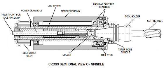
d) Power draw bolt for tool
clamp/unclamp mechanism: The power draw bolt is a critical mechanical element
used in CNC machine spindles for automated tool changing or ATC operation. It
consists of a drawbar and CAM mechanism located on the inner side of the
spindle. The drawbar and CAM mechanism securely clamp the tool holder inside
the spindle. The back end of the drawbolt has a tool holder retention or pull
stud, which ensures that the tool holder remains firmly attached to the tapered
nose and prevents it from coming out of the spindle. The tool holder is clamped
inside the spindle nose with the help of Schnorr springs or disc springs,
providing strong retention. An unclamped cylinder is used to release the tool
holder from the spindle by applying pressure against the spring tension. The
cylinder pushes the power draw bolt to the exact position required for easy
detachment of the tool holder from the spindle nose. A cross-sectional view of
a spindle illustrates the power draw bolt and the spindle's tool clamp/unclamp
mechanism.
e) Spindle Orientation
Mechanism: The spindle orientation mechanism is used to stop the spindle at a
specific position during automatic tool changing in a CNC machine. This
mechanism is located on the rear side of the spindle. When the spindle stops, a
small piston, usually operated hydraulically, moves through a small notch on
the rotating part of the spindle and stops at a specific position. This
prevents any spindle movement during the tool change operation and is known as
the spindle keylock condition. A proximity sensor is used to ensure accurate
insertion and completion of the spindle key lock. By further rotating the
spindle, the extended piston rod retracts, allowing the spindle to rotate
freely. Nowadays, some modern CNC machines utilize the "servo lock"
state of a spindle servo motor for spindle key lock, eliminating the need for
the previous system.
Integral
Spindle:
An Integral
spindle is a type of spindle unit that rotates using a servo motor, eliminating
the need for a spindle pulley and timing belt. The motor and spindle are
assembled together in a standard frame, resulting in lower noise and vibration
during spindle rotation. This design allows for higher rpm (revolutions per
minute) with an Integral spindle, which is essential for CNC machines that
require 10000 or more spindle rpm. Additionally, an Integral spindle always
comes equipped with a cooling system. However, it is usually more expensive
than a standard spindle. The following picture shows an Integral spindle.

A lead screw is a simple power transmission system that converts rotary motion into linear movement. It consists of a rotating threaded screw and a nut that slides over it to shift the load or transmit power. The screw is rotated by a motor, and the linear movement is achieved through the nut. A lead screw is commonly used to drive the motion of an axis. However, it has direct sliding contact between the nut and screw, resulting in higher friction and lower efficiency. Despite this drawback, a lead screw can carry a large load and is less expensive compared to other options. It is primarily found in cheaper CNC and conventional machines. The following picture shows a lead screw assembly.

Re-circulating
ball screw:
A Re-circulating ball screw is an advanced mechanical power transmission system used in mechatronic systems like CNC machines. It precisely converts rotary motion into linear motion. The ball screw rotates through servo motors, and the linear motion is obtained on the machine bed through a ball-screw nut assembly. Unlike a lead screw, a re-circulating ball screw significantly reduces sliding friction by incorporating rolling movement with a series of balls. This enhances the smoothness of axis movement and reduces friction. Additionally, a re-circulating ball screw requires a lower-capacity motor to overcome higher loads compared to a lead screw system. The following picture shows a ball screw and nut system.

In the previous picture, the balls rotate inside the screw and nut assembly. After reaching a certain point, the balls turn around and re-circulate through a return path, hence the term "re-circulating." Two types of re-circulating ball screw systems are commonly used: re-circulation through the insert channel and re-circulation via an external tube. The following picture shows both types of re-circulating ball screw systems.

As rolling balls are employed to eliminate sliding friction between the screw and nut, the ball-screw thread profile is also rounded. There are two types of rounded thread ball screws commonly used in ball-screw and nut systems: circular arc and gothic arc types. The circular arc-type has two contact points with the screw thread, while the gothic arc type has four contact points with the screw thread. The following picture shows both types of ball screw threads.

Difference between the lead screw and ball screw
The main difference between a ball screw and a lead screw lies in the way the load is carried between the moving surfaces. A ball screw utilizes re-circulating ball bearings to minimize friction and maximize efficiency, whereas a lead screw relies on low friction between sliding surfaces. Consequently, a lead screw typically cannot achieve the same level of efficiency as a ball screw. A lead screw utilizes deep helical threads and a mating nut, usually made of polymer composite or bronze. On the other hand, a ball screw employs a screw and nut assembly with matching helical grooves, allowing ball bearings to re-circulate inside the grooves. The screw thread and nut are typically semi-circular to accommodate the rotation of spherical steel balls. The following pictures show the screw and nut configurations of ball-screw and lead screw systems.

Roller screw:
A roller screw
is another mechanism used to convert rotary motion into linear motion. It
offers several advantages over a ball screw, including higher load-carrying
capacity, linear speed, tolerance, and accuracy. Roller screws also rotate with
servo motors and the linear movement is achieved through a nut assembly
connected to the machine bed. Two classes of roller screws are commonly used in
mechatronic systems: planetary and re-circulating types. Planetary roller
screws feature threaded rollers while re-circulating roller screws employ
circular groove rollers. The main difference between the two lies in their
roller designs. A roller screw ensures backlash-free movement in machine axis
drives and is more efficient than a ball screw. The following pictures show
typical roller screws used in mechatronic systems.

The rack and pinion mechanism is commonly used to convert rotary motion into linear movement. In this mechanism, the driving force is applied to the pinion gear by a motor, and linear displacement is transmitted through the rack mechanism. It can also be used as an indexing mechanism, where the linear movement is applied to the rack gear by a linear actuator and the rotary motion is obtained from the pinion gear. The pinion gear rotates with controlled rotation of the driving motor to achieve controlled linear displacement. Similarly, for steady indexing, the rack gear rotates through the controlled linear displacement of an actuator, usually achieved through the movement of a hydraulic or pneumatic cylinder's piston. The following picture illustrates a simple rack and pinion mechanism.

Gearbox:
A gearbox is a
mechanical device used to increase or decrease the speed or revolutions per
minute (RPM) of a rotating element. It is commonly employed as a torque-transmitting element in mechatronic systems. The gearbox consists of
different-sized gears arranged in a particular configuration to create a gear
train inside the gearbox assembly. This arrangement allows for the desired
output based on the gear ratio. The gearbox is typically used in conjunction
with an induction motor, where the drive shaft is attached to one end of the
gearbox, and the output shaft delivers the desired RPM. The gearbox also helps
reduce the load inertia reflected on the motor shaft by reducing the motor
speed. The motor shaft and output shaft may not be coaxial or parallel, making
the gearbox suitable for use in mechatronic systems or CNC machines. Some types
of gearboxes used in modern machinery include the sliding mesh, constant-mesh,
synchromesh, and epicyclic. The following picture shows a typical sliding
mesh-type gear assembly inside a gearbox.

Belt and
Pulley Mechanism:
Belts and
pulleys are commonly used mechanisms for transmitting torque in various systems
such as mechatronics systems, CNC machines, elevators, cranes, etc. They are
especially useful for transmitting power over long distances. A simple belt and
pulley mechanism consists of two pulleys and a belt. The belt is wrapped around
the two pulleys, with one pulley acting as the driving pulley and the other as
the driven pulley. There are two types of belt and pulley mechanisms used in
mechatronics systems.
V-Belt and Pulley: V-belts and pulleys are used to transmit power between two parallel axles. The V-belt has a cross-sectional shape that resembles a V. It is commonly used in automobile and conveying systems, as well as in some mechatronics systems. For high-power transmissions, multiple V-belts are arranged side-by-side in a configuration called a multi-V drive. These belts run in multi-grooved matching pulleys. V-belts are typically made of rubber or polymer, with embedded fibers (such as cotton, nylon, or steel) for added strength and support. The following picture shows a typical V-belt and pulley system.

Timing Belt and Pulley: The timing belt and pulley is a torque-transmitting element that transfers torque from one rotating shaft to another, sometimes with an expanded or reduced speed. It consists of a rotary actuator, such as a motor, coupled with a smaller diameter driver pulley to reduce the rotating speed. The rotating element is connected to a larger diameter driven pulley, which reverses the process to increase the rotating speed. The timing belt, usually made of rubber, functions like a gear and provides flexibility similar to a V-belt. Unlike a V-belt, there is no slippage, and this system does not have the sound or lubrication issues associated with gearbox mechanisms. A timing belt always works in conjunction with a pair of timing pulleys, which have axial grooves that match the teeth on the timing belt. As the timing belt rotates, its teeth engage smoothly with the grooves on the pulleys, generating no friction or noise. Timing belts are typically made by helically winding a steel or glass fiber wire to create a base that can carry the load. The belt's surface is then molded with materials like neoprene or polyurethane elastomer to form the belt teeth, while pulleys are commonly made of aluminum alloy or iron. The following picture shows a timing belt and pulley assembly.

Sprocket &
Chain Mechanism:
A sprocket and chain mechanism is another commonly used method for transmitting motion and force efficiently. Sprockets are rotating parts with teeth that are integrated with a roller chain, which is typically connected in a continuous loop. Sprockets are placed on parallel shafts and are always on the same plane. One sprocket acts as the driver sprocket, while the other serves as the driven sprocket. The sprockets have multiple teeth around their circumference, and the roller chain consists of inner and outer links that are connected to form a flexible strand. Sprockets and chains are effective for transmitting torque over long distances. One advantage of using a chain and sprocket drive over a belt drive is that the chain cannot slip over the sprocket due to the teeth, which prevents slippage. However, a disadvantage is that this system is usually noisier and more expensive than a belt drive. The following picture shows a sprocket and chain drive mechanism.

Clutch:
A clutch is a
mechanism used to engage and disengage power transmission between a driving
shaft and a driven shaft. It connects and disconnects two rotating shafts.
There are different types of clutches used in mechatronics systems, each with
its own advantages and applications based on their torque/power transmission
capacity and design. Some common clutch mechanisms include:
Single-plate
clutch: A single-plate clutch consists of two friction discs, and torque
transmission occurs when both discs come into contact with each other. One disc
is connected to the input shaft, while the other is coupled to the pressure
plate and can slide on a shaft. The pressure plate is attached to a
pre-compressed spring, which applies axial force on the other disc.
Multi-plate
clutch: Similar to a single-plate clutch system, a multi-plate clutch consists
of multiple friction discs. The presence of multiple discs increases the
contact area, allowing for greater torque transmission. The entire clutch
assembly and plates are filled with oil.
Cone clutch: A
cone clutch comprises two male and female drums. The male drum is attached to a
motor shaft and has an internal friction lining, while the female drum is fixed
with a splined shaft and has an outer friction lining. When the clutch is
engaged, the female cone fits inside the male cone and they rotate together.
Centrifugal
clutch: In a centrifugal clutch, there is a hub at the center coupled with the
prime mover. Multiple shoes, attached to the hub via springs, have friction
material on their outer surface. The clutch movement is achieved through
centrifugal force.
Hydraulic
clutch: A hydraulic clutch uses fluid to actuate a hydraulic piston. It has a
reservoir containing hydraulic fluid. When the clutch pedal is pressed, the
fluid becomes pressurized and works in conjunction with the clutch plate to
engage and disengage gears. The hydraulic clutch is commonly used to connect or
disconnect the engine from the transmission when the driver changes gears.
Electromagnetic
clutch: Electromagnetic clutches function electrically to transmit torque
mechanically. They consist of an armature on the driven shaft and an
electromagnet on the driving shaft. When a current flows through the
electromagnet, it creates a magnetic field that attracts the armature,
generating a frictional force between the friction plates. To disengage the
clutch, the electric supply is stopped, and a spring tension retracts the
position of the armature.

Coupling:
A coupling is
a component that serves as a torque-transmitting element and creates a strong
connection between two rotating shafts. Couplings are typically classified into
two types: rigid and flexible couplings. Rigid couplings are primarily used when
two shafts are coaxial, meaning they are on the same axis. Flexible couplings
are employed when the connecting shafts are not always coaxial and there is a
possibility of shocks in the transmission. Flexible couplings are also known as
elastic couplings and are used when there is minor misalignment between two
shafts. For example, a flexible coupling may be used to connect a CNC machine
axis servo motor with a ball screw, while rigid couplings are commonly used in
induction motor-driven pumps such as hydraulic pumps or coolant pumps. The
following pictures show two types of couplings.

Various flexible couplings are used in different mechatronics systems for various purposes. The left picture shows a flexible coupling connected to a servo motor with a ball screw, while the other picture demonstrates how flexible couplings can overcome misalignments.

Taper Lock
Bush:
Taper lock bushes are used to create a rigid and strong connection between gear shafts or timing pulleys and a motor. This system involves a bush with a tapered or conical outer side. The bush has a slit and can be inserted into a taper lock hub, which has a tapered bore with a matching angle to the bush. When these two elements (the bush and the hub) are positioned on a shaft, such as a motor shaft, and tightened with screws, the bush's slit gradually closes and tightly grips the shaft placed inside the bush. This entire system securely transmits torque from the shaft to the hub or vice versa, without any backlash. The following picture shows a simple taper lock bush system.

Worm and Worm Wheel:
In mechatronics systems, screws, worm and gear, or worm wheel are commonly used to transmit rotary motion between different planes. When a motor rotates the worm, the coupled worm wheel also turns, transmitting rotary motion from one plane to another. Worm and worm wheel systems are often found in CNC machines for rotary axis movement. The servo motor is coupled with the worm shaft to rotate, and the rotary axis movement is achieved through the movement of the worm wheel. The teeth of the worm and worm wheel are usually bent or curved to increase the linkage between them. This system, known as Enveloping or Globoid, allows torque to be evenly distributed among the numerous teeth, enabling the rotation of worm and worm wheels while carrying heavy loads. The picture below illustrates a typical worm and worm wheel system.

Cam and Follower:
A cam is a mechanical component that converts rotary motion into oscillating movement, which is then transferred to the follower to produce the desired output. This mechanism guides the follower along a predetermined path and can also transform rotary motion into different step movements. Cam and follower systems are reliable and accurate indexing mechanisms frequently utilized in mechatronics systems, such as the automatic tool-changing system in CNC machines. Typically, the cam and follower consist of two separate units: the cam itself and the follower. When an induction motor imparts rotary motion to the cam unit, the follower produces the corresponding oscillating movement. Various types of cam-follower mechanisms exist in different mechatronics systems, including rotating cam with translating follower, rotating cam with oscillating follower, translating cam with translating follower, and stationary cam with moving follower. Different types of cams, such as disk or plate, cylindrical, translating, wedge, spiral, and heart-shaped cams, are available, along with various followers like a knife-edge, roller, flat-faced, spherical, radial, and offset followers. The efficient cam drive mechanism enables the conveyance of multiple complex movements within a mechatronics system. The picture below illustrates a cylindrical and complex cam drive mechanism used in the automatic tool-changing operation of a CNC machine.

Ratchet and Pawl Mechanism:
The ratchet and pawl mechanism is an indexing mechanism employed to drive linear or rotary motions in one direction only while restricting reverse movements. This system consists of a ratchet with a gear wheel and two pawl mechanisms: a driving pawl and a locking pawl. The locking pawl is angled in association with the gear teeth, allowing it to move freely over the gear teeth in one direction only. If the ratchet gear assembly attempts to rotate in the opposite direction, the locking pawl engages with adjacent gear teeth through spring tension, restricting the reverse movement of the gear. An arm attached to the driving pawl permits the gear to rotate in one direction only and is typically driven by a linear actuator, such as a cylinder stroke. The picture below illustrates a simple ratchet and pawl mechanism.

Geneva Mechanism:
The Geneva mechanism is another indexing system used to obtain irregular or intermittent rotary movement from continuous rotary motion. It comprises two different wheels: a drive wheel and a Geneva wheel. The driver wheel rotates continuously driven by a motor, while intermittent rotary motion is obtained from the Geneva wheel. In this system, a pin is rigidly placed on the driver wheel in such a way that, as the wheel rotates, the pin can pass through slots on the Geneva wheel one after another. The picture below illustrates a simple Geneva mechanism. With this system, each complete rotation of the driver wheel (360°) produces a 90° intermittent rotary movement on the Geneva wheel, resulting in four-step movements for a full rotation. The step movements of the Geneva wheel can be adjusted by changing its configuration. The application of the Geneva mechanism is limited to various mechatronics systems.


.png)


