Thursday, July 6, 2023

Canned cycle

What is a canned cycle?

Canned cycles are commonly used to simplify complicated machining operation programming. Different canned cycles are typically applied for repetitive machining tasks such as drilling, boring, and tapping. They are selected or activated using various G-codes and canceled using the G80 code. In a canned cycle, the X and Y-axis movements are executed with a Rapid command, while the Z-axis motion is controlled with the Feed command. Canned cycles help reduce program memory since fewer blocks are required compared to non-canned cycle programming. The following parameters are typically used in simple canned cycle programming:

X & Y –            Hole position data 

Z –                   Distance from point ‘R’ to the bottom of the hole 

R –                  Retract plane

Q –                  Depth of cut for each cutting feed

F –                   Cutting feed rate

K –                   Number of repeats


1. Drilling Cycle (G81)


N5 T1 M06                                 (Drilling tool changing)

N10 G00 G90 G54 X20 Y60      (Positioning over the drilling point with zero offsets)

N15 M03 S2000                         (Spindle ON)

N20 G00 G43 H01 Z1 M07       (Rapid positioning Z-axis with tool offset)

N25 G81 G99 Z-41 R1 F10       (Drilling cycle on & returning to R point after completion)

N30 G80 G28 X0 Y0 Z0            (Cancelling canned cycle and returning home position) 

N35 M05 M09                            (Spindle stop & Coolant off)

N40 M30                                     (End of the program)
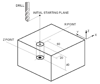

2. Peck Drilling Cycle (G83)


N5 T2 M06                                         (Drilling tool changing)

N10 G00 G90 G54 X20 Y60              (Positioning over the drilling point with zero offsets)

N15 M03 S2000                                 (Spindle ON)

N20 G00 G43 H01 Z1 M07               (Rapid positioning Z-axis with tool offset)

N25 G83 G99 Z-61 Q20 R1 F10       (Peck drilling cycle on & returning to R point)

N30 G80 G28 X0 Y0 Z0                    (Cancelling canned cycle and returning home position) 

N35 M05 M09                                    (Spindle stop & Coolant off)

N40 M30                                             (End of the program)


3. Tapping Cycle (G84)


N5 T3 M06                             (Tapping tool changing)

N10 G00 G90 G54 X20 Y60  (Positioning over the drilling point with zero offsets)

N15 S200                               (M03 not required, as G84 will turn ON the spindle)

N20 G00 G43 H01 Z1 M07   (Rapid positioning Z-axis with tool offset)

N25 G84 G99 Z-41 R1 F10   (Tapping cycle on & returning to R point after completion)

N30 G80 G28 X0 Y0 Z0        (Cancelling canned cycle and returning home position) 

N35 M05 M09                        (Spindle stop & Coolant off)

N40 M30                                 (End of the program)


4. Bore in & Bore out canned cycle (G85)  


N5 T3 M06                             (Boring tool changing)

N10 G00 G90 G54 X20 Y60  (Positioning over the drilling point with zero offsets)

N15 M03 S1000                     (Spindle ON)

N20 G00 G43 H01 Z1 M07   (Rapid positioning Z-axis with tool offset)

N25 G85 G99 Z-41 R1 F10   (Boring cycle on & returning to R point after completion)

N30 G80 G28 X0 Y0 Z0        (Cancelling canned cycle and returning home position) 

N35 M05 M09                        (Spindle stop & Coolant off)

N40 M30                                 (End of the program)


Turning Programming Examples

The following examples demonstrate different turning operations carried out using CNC turning/lathe machines. Specifically, we will concentrate solely on finish turning processes, excluding any discussion on rough turning operations.

Example – 1   


% 1111 (Program number)
(Example-1)                          (Program name)
N5 G21 G90 G54                  (Preparatory function code)
N10 T1 D1                            (T1 cutting tool with D1 offset)
N15 M03 S2000 M08           (Spindle & Coolant ON)
N20 G00 G54 X160 Z0        (Positioning at B point with zero offsets)
N25 G01 G41 X-2 F0.05      (Facing with tool nose comp. left up to C point)
N30 G42 X30                        (Positioning at D point with tool nose comp. right)
N35 Z-20                              (Positioning at E point)
N40 X110                              (Positioning at F point)
N45 Z-40                              (Positioning at G point)
N50 X80                              (Positioning at H point)
N55 Z-55                             (Positioning at I point)
N60 X150 Z-85                     (Positioning at J point)
N65 Z-105                             (Positioning at K point)
N70 X80                                 (Positioning at L point)
N75 Z-125                             (Positioning at M point)
N80 X150                              (Positioning at N point)
N85 Z-145                              (Positioning at O point)
N90 X110                                 (Positioning at P point)
N95 Z-165                             (Positioning at Q point)
N100 X160                              (Positioning at R point)
N105 G00 G40 G53 X300 Y200 (Returning to A point)
N110 M05 M09                      (Spindle & Coolant OFF)
N115 M30                                  (End of the program)


Example – 2 


% 2222 (Program number)
(Example-2)                                     (Program name)
N5 G21 G90 G54                             (Preparatory function code)
N10 T2 D1                                       (T2 cutting tool with D1 offset)
N15 M03 S2000 M08                      (Spindle & Coolant ON)
N20 G00 G54 X30 Z0                     (Positioning at B with work offset)
N25 G01 G42 X-2 F0.05                 (Facing operation, considering tool nose compensation)
N30 X10                                          (Positioning X-axis)
N35 Z-30                                          (Z-axis movement, positioning at D point)
N40 G02 X60 Z-50 R20 F0.02         (Positioning at E point with CW 20 mm radius path)
N45 G03 X60 Z-90 I0 K-20 F0.02   (Positioning at F point with CCW 20 mm radius path)
N50 G01 Z-120 F0.05                      (Positioning at G point)
N55 X110                                         (Positioning at H point)
N60 G00 G40 G53 X300 Z200         (Returning to tool changing position A)
N65 M05 M09                                  (Spindle & Coolant OFF)
N70 M30                                          (End of the program)

Example – 3


% 3333                                                   (Program number)
(Example-1)                                           (Program name)
N5 G21 G90 G54                                   (Preparatory function code)
N10 T3 D1                                              (T3 cutting tool with D1 offset)
N15 M03 S2000 M08                             (Spindle & Coolant ON)
N20 G00 G42 X90 Z0                            (Positioning with tool nose radius compensation)
N25 G01 X-2 F0.05                               (Facing operation)
N30 X15                                                 (Positioning X-axis)
N35 X30 Z-20                                        (Linear interpolation movement of X & Z axes)
N40 Z-90                                                (Positioning Z-axis)
N45 G02 X50 Z-100 R10 F0.02            (Circular movement with 10 mm radius)
N50 G01 Z-140 F0.05                           (Positioning Z-axis)
N55 X90                                                (Positioning X-axis)
N60 G00 G53 X200 Z200                    (Returning to tool change position)
N65 M05 M09                                      (Spindle & Coolant OFF)
N70 M30                                              (End of the program)

Example – 4


% 4444 (Program number)
(Example-4)                                                      (Program name)
N5 G21 G90 G54                                              (Preparatory function code)
N10 T4 D1                                                         (T4 cutting tool with D1 offset)
N15 M03 S2000 M07                                        (Spindle & Coolant ON)
N20 G00 G54 X30 Z0                                        (Positioning with work offset)
N25 G01 G42 X-2 F0.05                                    (Facing operation)
N30 X20                                                             (Positioning X-axis)
N35 X100 Z-40                                                  (X & Z axis synchronized movement)
N40 G03 X100 Z-90 I-16.58 K-25 F0.02          (Circular movement with 30 mm radius path)
N45 G01 Z-120 F0.05                                         (Positioning Z-axis)
N50 G02 X100 Z-170 I16.58 K-25 F0.02          (Circular movement with 30 mm radius path)
N55 G01 X150 F0.05                                          (Positioning X-axis)
N60 G00 G40 G53 X300 Z200                          (Returning to tool changing position)
N65 M05 M09                                                    (Spindle & Coolant OFF)
N70 M30                                                             (End of the program)

Milling Programming Examples

Example – 1

The dimensions of the workpiece blank are as follows: length = 110 mm, breadth = 110 mm, and thickness = 5 mm. An end-mill cutter with a diameter of 10 mm will be used for machining purposes.

%1111

(Example 1)

N05 G21 G90 G94                             (Preparatory function codes)

N10 T1 M06                                       (T1 number tool change)

N15 M03 S2000 M07                         (Spindle ON with 2000 RPM & Coolant ON)

N20 G00 G54 D1 X-10 Y0 Z5          (Axis positioning considering work offset & tool offset)

N25 G01 Z-5.5 F150                          (Z-axis movement for the depth of cut)

N30 G41 X0 Y0                                 (Cutter compensation left & positioning at A point)

N35 Y75                                             (Positioning at B point)

N40 X25 Y100                                   (Positioning at C point) 

N45 X50                                             (Positioning at D point)

N50 Y75                                             (Positioning at E point)  

N55 X100                                           (Positioning at F point)

N60 Y15                                             (Positioning at G point)  

N65 G02 X85 Y0 R15 F100              (Positioning at H point with 15 mm radius path)

N70 G01 X0 F150                              (Return to position A)

N75 G00 G40 X-15 Y-15                   (Cancelling cutter compensation and shifting axes)  

N80 Z5 M05 M09                               (Retracting Z-axis, Spindle stop, and Coolant off)

N85 G00 G53 X0 Y0 Z0                    (Cancelling work offset & returning to machine zero)

N90 M30                                             (End of the program)


Example – 2 

The dimensions of the workpiece blank are as follows: length = 310 mm, breadth = 160 mm, and thickness = 10 mm. An end-mill cutter with a diameter of 10 mm will be used for machining purposes.


%2222

(Example 2)

N05 G21 G90 G94                             (Preparatory function codes)

N10 T2 M06                                       (Tool change)

N15 M03 S1000 M07                         (Spindle & Coolant ON)

N20 G00 G54 D1 X-10 Y0 Z-5          (Axis positioning with work offset & tool offset)

N25 G01 Z10.5 F200                         (Z-axis movement for the depth of cut)

N30 G42 X0 Y0                                 (Cutter compensation Right & positioning at A point))

N35 Y70                                             (Positioning at B point)

N40 X30                                             (Positioning at C point) 

N45 X100 Y150                                 (Positioning at D point)

N50 X140                                           (Positioning at E point)  

N55 Y110                                           (Positioning at F point)

N60 G02 X220 Y110 R40 F100        (Positioning at G point with 40 mm radius path)  

N65 G03 X300 Y110 R40 F100        (Positioning at H point with 40 mm radius path)

N70 G01 Y0 F200                              (Positioning at I point) 

N75 X280                                           (Positioning at J point)

N80 G02 X200 Y0 R40 F100            (Positioning at K point with 40 mm radius path)  

N85 G01 X180 F200                          (Positioning at L point)  

N90 Y40                                             (Positioning at M point)  

N95 X140                                           (Positioning at N point)

N100 G03 X60 Y40 R40 F100          (Positioning at O point with 40 mm radius path)  

N105 G01 X30 F200                          (Positioning at P point)

N110 Y0                                             (Positioning at Q point)

N115 X0                                             (Returning at A Point)

N100 G00 G40 X-15 Y-15                 (Cancelling cutter compensation and shifting axes)  

N105 Z5 M05 M09                             (Retracting Z-axis, Spindle stop, and Coolant off)

N110 G00 G53 X0 Y0 Z0                  (Cancelling work offset & returning to machine zero)

N105 M30                                           (End of the program)


Example – 3

The dimensions of the workpiece blank are as follows: length = 130 mm, breadth = 110 mm, and thickness = 10 mm. An end-mill cutter with a diameter of 10 mm will be used for machining purposes.


%3333

(Example 3)

N05 G21 G90 G94                             (Preparatory function codes)

N10 T3 M06                                       (Tool change)

N15 M03 S3000 M07                         (Spindle ON with 3000 RPM & Coolant ON)

N20 G00 G54 D1 X-10 Y0 Z5          (Axis positioning considering work offset & tool offset)

N25 G01 Z-10.5 F200                        (Z-axis movement for the depth of cut)

N30 G41 X0 Y0                                 (Cutter compensation left & positioning at A point)

N35 Y85                                             (Positioning at B point)

N40 G02 X15 Y100 F100                  (Positioning at C point with 15 mm radius path) 

N45 G01 X45 F200                            (Positioning at D point)

N50 G02 X65 Y80 I20 J0 F100         (Positioning at E point with 20 mm radius path)  

N55 G01 Y60 F200                            (Positioning at F point)

N60 X85                                             (Positioning at G point)  

N65 G02 X100 Y45 R15 F100          (Positioning at H point with 15 mm radius path)

N70 G01 Y40 F150                            (Positioning at I point) 

N75 G02 X90 Y30 R10 F100            (Positioning at J point with 10 mm radius path)

N80 X85                                             (Positioning at K point)  

N85 G03 X65 Y10 I-20 J0 F100        (Positioning at L point with 20 mm radius path)  

N90 Y0                                               (Positioning at M point)  

N95 X0                                               (Positioning at A point)  

N100 G00 G40 X-15 Y-15                 (Cancelling cutter compensation and shifting axes)  

N105 Z5 M05 M09                             (Retracting Z-axis, Spindle stop, and Coolant off)

N110 G00 G53 X0 Y0 Z0                  (Cancelling work offset & returning to machine zero)

N105 M30                                           (End of the program)


Example – 4 

The dimensions of the workpiece blank are as follows: length = 170 mm, breadth = 170 mm, and thickness = 80 mm. An end-mill cutter with a diameter of 10 mm will be used for machining purposes.

%4444

(Example 4)

N05 G21 G90 G94        

N10 T4 M06                                       (Considering 10 mm diameter end-mill)      

N15 M03 S1500 M07       

N20 G00 G54 G42 D1 X0 Y0 Z-85  (Z-axis positioning 5 mm above work-piece)

N25 G01 Z-20 F150                           (Z-axis taking the depth of cut 20 mm)

N30 X10                                             (Cutter entering work-piece 10 mm)

N35 Y180                                           (Making 10 mm slot on work-piece)

N40 G00 Z-85                                    (Z-axis return 5 mm above work-piece) 

N45 G00 X20 Y0                               (Positioning for the second cut)

N50 G01 Z-20 F150                           (Again cutter entering work-piece)  

N55 Y180                                           (Finishing to make 20 mm slot)

N60 G00 Z-85                                    (Z-axis return 5 mm above work-piece)  

N65 G00 G41 X160 Y0                     (Positioning for first circular cutting)

N70 G01 Z-20 F150                           (Cutter downward for first circular cut)

N75 G02 X170 Y10 R30 F100          (First circular cut)  

N80 G00 Z-85                                    (Z-axis return 5 mm above work-piece)  

N85 G00 X150 Y0                             (Positioning for Second circular cutting)

N90 G01 Z-20 F150                           (Cutter downward for Second circular cut)

N95 G02 X170 Y20 R30 F100          (Second circular cut)  

N100 G00 Z-85                                  (Z-axis return 5 mm above work-piece)  

N105 G00 X140 Y0                           (Positioning for Third circular cutting)

N110 G01 Z-20 F150                          (Cutter downward for Third circular cut)

N115 G02 X170 Y30 R30 F100        (Third circular cut)  

N120 Z-85 M05 M09                          (Retracting Z-axis, Spindle stop, and Coolant off)

N125 M30                                           (End of the program)


Popular Posts