Limit switch:
A limit switch is a simple digital contact-type sensor
commonly used in various mechatronics systems to send position signals of a
moving appliance. Typically, a limit switch provides two types of signal
outputs: Normally Closed (NC) and Normally Open (NO). The picture below shows
the internal view of a general type of limit switch.

The limit switch usually
consists of a mechanical plunger that can move against spring tension. By
applying force to the top of the plunger, it is pushed downward and returns to
its original position when the pressure is released. A small snap switch is attached
to the plunger and activates or deactivates based on the plunger movement. The
snap switch used inside the limit switch is a special type that includes a tiny
plunger on top of the switch with a movable contact. This contact changes its
position between two fixed contact points, exerting slight pressure on the
plunger. In the normal state, the movable contact always connects to one fixed
contact point, and when the plunger is pressed, it changes position and
connects to the opposite fixed contact. The stationary contacts are normally
considered as NC, while the opposite connection is the NO contact. The pictures
depict the internal view of a snap switch operated within a limit switch.

Different types of snap
switches can be found inside a limit switch, depending on the current-carrying
capacity and plunger design. Typically, limit switches utilize micro-snap
switches with a capacity of 250 V and 5 Amperes, suitable for mechatronics
systems. Various limit switches are available, offering different designs such
as roller type, pin type, and more.
Inductive proximity sensor:
An inductive proximity
sensor is the most commonly used non-contact digital sensor in mechatronics
systems. Inductive proximity switches come in different types based on their
construction and functionality, such as NPN or PNP type, plug or cord type, and
more. However, the basic working principle remains the same for different
inductive proximity switches. The block diagram below illustrates an inductive
proximity sensor commonly found in CNC machines.

The left-side picture shows
an inductive proximity switch constructed with four components: a coil,
oscillator, trigger circuit, and output switching circuit. A coil is typically
wrapped on the head face of the proximity switch, just beneath the sensing
face. The output of the oscillator circuit is fed to the coil, creating an
alternating magnetic field in front of the switch, known as the sensing field.
This magnetic field extends outside the proximity switch through a non-metallic
lining. When a metallic object like iron, copper, aluminum, or steel comes
closer to the alternating magnetic field, it induces an eddy current within
that object. The eddy current causes a power loss in the oscillator circuit. As
the metallic object gets nearer to the proximity switch, the power loss
increases, exerting pressure on the output of the oscillator circuit and
reducing the amplitude of the oscillator output (see the right-side picture).
Once the amplitude drops below a specific threshold level, the oscillation of
the oscillator circuit stops due to the loading caused by the eddy current. At
this point, the trigger circuit detects the output of the oscillator circuit
and turns on the output switching circuit. The sensing distance of a proximity
switch indicates its capability to sense metallic objects up to a maximum
distance from the sensing face, which typically depends on the diameter of the
sensing coil. A smaller diameter inductive proximity switch has a shorter
sensing distance, while a larger one has a longer sensing distance. It's
important to note that the sensing distance of the same proximity switch may
vary with different sensing objects due to their material properties.

A proximity switch usually
has three terminals: positive (+), negative (-), and a switching output
terminal. By supplying both the positive and negative terminals (typically
using a 24 V DC supply) and sensing it externally, a 24 V DC output can be
obtained from the switching output terminal. Proximity switches are commonly available
in two types: PNP and NPN. For a PNP-type proximity switch, the switching
output is obtained with respect to the negative terminal, while for an NPN
type, it is considered with respect to the positive terminal (as shown in the
earlier pictures). Sometimes, a single proximity switch can provide both
Normally Closed (NC) and Normally Open (NO) switching outputs, resulting in
four terminals. An LED is typically included to indicate whether the proximity
switch is sensing or not.
Capacitive proximity sensor:
A capacitive proximity
sensor is another type of non-contact digital sensor used to sense non-metallic
objects and, occasionally, liquid levels. Capacitive proximity sensors or
switches can be categorized into two types: dielectric and conductive. Inside a
capacitive proximity switch, two plates are positioned in front of the sensing
surface, and the sensing object acts as a dielectric between these plates. When
the sensing object comes within a certain distance in front of the sensing
face, the capacitance value reaches a specific level, triggering a built-in
trigger circuit inside the switch and generating a switching output. Capacitive
proximity switches are generally more expensive than inductive proximity
switches, and their applications are limited in mechatronics systems. The
picture below shows a capacitive proximity sensor.

Infrared Sensor:
An infrared sensor is a
non-contact digital sensor used to detect opaque and non-metallic objects from
a long distance. There are three types of infrared sensors: Thru-beam type,
Diffuse reflective type, and Retro-reflective type. In mechatronics systems,
infrared sensors are commonly used to sense opaque objects from a distance. The
picture below shows a typical infrared sensor.

Thru-beam Infrared sensor -
This type of sensor consists of two separate units: an emitter and a receiver
(see the picture), both placed on opposite sides of the sensing object. The
emitter unit transmits an infrared light beam, which falls directly on the
receiver unit through a lens. If an opaque object obstructs the infrared light
beam falling on the receiver unit, a switching circuit inside it is activated,
providing the necessary sensing output. The great advantage of using this
sensor is its long sensing range, but a disadvantage is that it requires two
separate wirings for the emitter and receiver units.

Diffuse reflective Infrared
sensor - Here, the emitter and receiver are assembled in a single unit. An
infrared light beam from the emitter falls on an opaque object through a lens,
and the reflected light returns to the receiver segment, turning a switching
circuit ON or OFF depending on the presence or absence of the light beam. This
sensor is more manageable than the Thru-beam type as it uses a single unit
instead of two separate units. The sensing distance of this sensor is always
shorter than that of a Thru-beam type sensor, and it requires a bright or shiny
surface as the sensing object.

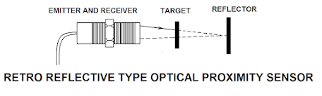
Retro-reflective Infrared
sensor - These are the most commonly used sensors in mechatronic systems
compared to the other two types. Both the emitter and receiver are assembled in
the same unit, similar to the Diffuse-reflective type sensor. A reflector is
always used with this sensor, and the infrared light beam transmitted from the
emitter is reflected directly from the reflector back to the sensor receiver.
When an opaque object appears between the reflector and sensor, the light beam
is obstructed, and the sensor turns ON an output switching circuit, indicating
the presence of an infrared light source. Operating this sensor is very
convenient in any mechatronics system as only one device is required for
wiring. The sensing distance is also very high when using a reflector. However,
this sensor cannot be used with shiny or reflective surfaces.
Pressure Sensor:
A pressure
sensor or pressure switch is a digital contact-type sensing element used to
measure the exact pressure level in hydraulic or pneumatic systems. When there
is significant pressure inside a pressure line, it activates a small 'Snap
switch' and provides a sensing output. The switching output can be either
Normally Closed (NC) or Normally Open (NO). A diaphragm or piston is typically
fitted inside a pressure switch, influenced by fluid pressure against spring
tension, and it activates the snap switch. When the fluid pressure ceases, the
snap switch plunger returns to its initial position due to spring tension. The
picture below shows a hydraulic pressure switch and its internal configuration.
A pressure switch usually has a pressure adjustment knob (see picture) to set
the required pressure for switch activation. By adjusting the innerspring
tension through a screw, the necessary fluid pressure to activate the snap
switch can be increased or decreased. Pressure switches are usually built with
different designs and sensing media or elements, such as hydraulic pressure
switches and pneumatic pressure switches, among others.

Magnetic Sensor:
A magnetic sensor, commonly
known as a magnetic reed switch, is a non-contact digital sensor that activates
in the presence of a magnetic field. It consists of two tiny and thin iron
plates positioned inside a small glass container, with a small gap between
them. When a permanent magnet approaches the glass bulb, one of the inner
plates bends and connects to the other, acting as an electric switch. The
electrical contact is disconnected when the magnet moves away, returning the
plates to their original position. Switching contacts can be of either Normally
Open (NO) or Normally Closed (NC) types and are usually integrated into the
mechatronic system's magnetic sensor. The picture below shows how a 'Normally
Open' type magnetic sensor works.
Level Sensor or Float
Switch:
A level sensor or float
switch is a digital contact sensor used to measure the liquid level or height.
Most float switches work based on the buoyancy principle. A float is typically
set inside a float switch, which hovers on the liquid surface and swings upward
and downward depending on the liquid level. There is a small magnet inside the
float (see the picture), which turns ON or OFF a magnetic reed switch. The
magnetic reed switch is positioned inside a tube made of non-magnetic material,
allowing the floated magnet to activate the reed switch only when the float
reaches a specific position. As a result, the reed switch inside the float
switch only activates when the liquid level reaches a predetermined point. The
output of the float switch is used in mechatronic systems to specify different
liquid levels, such as cutting coolant, hydraulic oil, lubrication oil, etc.
The picture below shows the float switch and its interior.

Float switches are usually
of two types: vertical and horizontal float switches. A vertical float switch
is positioned at the top or bottom of a liquid tank, while a horizontal float
switch is fixed along the tank sidewall. The basic working principle for both
types of float switches is identical, but there are differences in their
construction. Sometimes, analog types of different liquid-level sensors are
also used, such as ultrasonic liquid-level sensors, optical liquid-level
sensors, hydrostatic liquid-level sensors, etc., to measure the liquid level
more precisely. However, the use of these liquid-level sensors with mechatronic
systems is limited.
Flow Switch:
A flow switch is a
contact-type digital sensor used to detect liquid flow through a pipeline.
There are usually two types of flow switches: Piston type and Shuttle type. The
picture below explains a piston-type flow switch and its interior.
The picture shows a
permanent magnet and a reed switch functioning inside a flow switch. In the
piston-type flow switch, the permanent magnet is attached to a piston, which
can move against spring tension. When fluid pressure is present in the inlet
line, both the piston and magnet move toward the inner side. A reed switch is
associated with the body (as shown in the picture) and activates or deactivates
with the movement of the permanent magnet. The output signal of a reed switch
can be either Normally Closed (NC) or Normally Open (NO), and it is considered an input signal for a mechatronic system. The basic working principle of a
Shuttle type flow switch is similar to that of a Piston type flow switch,
except a shuttle is used instead of a piston.
Flow Sensor:
A flow sensor
is an instrument capable of measuring the amount of liquid (usually water)
passing through an orifice. Different types of flow sensing technologies are
available, depending on the measurement techniques, such as Mechanical flow
meter, Ultrasonic flow meter, Magnetic flow meter, Thermal flow meter, etc. The
most common and cost-effective type is a mechanical flow meter, which measures
the flow by the rotation of a propeller or paddle-designed turbine wheel. The
rotor inside the flow sensor spins proportionally to the liquid flow and
generates pulses detected by a Hall effect sensor. By measuring the pulses per
second, the controller obtains information about the flow rate through the
orifice. The main disadvantage of using this type of flow meter is that it can
get clogged when the liquid is dirty or it may not function properly when the
water flow is too low. The picture below shows a turbine-type mechanical flow sensor
and its interior.
Temperature sensor:
The temperature sensor is
commonly used to measure the temperature or temperature changes of an object.
It is an analog-type sensor utilized in various applications such as
refrigerators, computers, motor control, processing industries, and
automobiles. There are three main types of temperature sensors: Thermistor,
Thermocouple, and Resistive Temperature Device (RTD), which are frequently
found in mechatronics systems. The output signal of the sensor is typically a
variable resistance or changing voltage, which is sometimes transmitted through
a suitable circuit.
Thermocouple - A
thermocouple is made by joining two different metals together, leaving one end
open (refer to the picture). The joined end is called the hot junction, while
the open end is known as the cold junction. When the hot junction is heated, a
small potential difference or voltage is generated between the terminals of the
cold junction. By measuring this voltage, a controller can determine the temperature
at the hot junction. The amount of voltage depends on the level of heating and
the properties of the thermocouple material. To obtain a proper sensing signal,
the voltage is passed through an amplifier and converter circuit, which makes
it compatible with the controller. Refer to the diagram below for a typical
thermocouple system.

Resistive Temperature Device
(RTD) - The resistive temperature device (RTD) operates based on the principle
that the electrical resistance of a metallic object changes with temperature.
It utilizes a length of metallic wire, typically made of platinum, as the
sensing element. As the temperature increases, the total resistance of the wire
changes, and this changing resistance is considered the output signal of the
RTD. Before applying the signal to the controller, it is passed through a
suitable circuit. RTDs are commonly used for extremely low and high-temperature
measurements. The diagram below illustrates how an RTD works.

Thermistor - The working
principle of a thermistor is similar to that of an RTD. However, instead of a
metallic wire, a polymer or ceramic material is used in a thermistor, making it
more cost-effective compared to an RTD. Most thermistors are of the negative
temperature coefficient (NTC) type, meaning their resistance decreases with
increasing temperature. Thermistors are suitable for low-temperature
measurements. The pictures below show a temperature sensor IC and an NTC
thermistor.
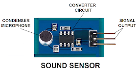
Sound sensor:
A sound sensor is a digital
sensor used to measure the intensity of sound or audio level. When the sound
reaches a certain threshold value, the sensor generates a signal voltage. It
consists of a small microphone that converts sound into an electrical signal
according to its intensity. The output signal from the microphone is sent to an
amplifier and then through a circuit to make it suitable for the controller. A
potentiometer is used with the sensor board to define the sound intensity at
which the sensor should act. Sound sensors are used in various applications,
including security systems, monitoring services, and switching applications.
Refer to the picture below for a sound sensor.
Light sensor:
A light sensor is an
analog-type sensor used to measure the intensity of light. It commonly employs
a silicon photodiode, which produces an analog voltage proportional to the
light intensity. Another type of light sensor is the Light Dependent Resistor (LDR),
which changes its resistance value based on the amount of light falling on it.
When no light is present, the resistance of the LDR is high, and as the light
intensity increases, the resistance decreases. The output of the LDR is usually
passed through a converter circuit to suit the requirements of the control
system. These sensors find applications in various fields, including the
machining industry, computers, and medical instruments. The pictures below show
an LDR and a light sensor.
Tilt sensor:
A tilt sensor is a digital
sensor used to detect the orientation or inclination of an object. It consists
of two conductive elements placed with a small gap inside a hollow glass
cylinder (refer to the picture). A small rolling ball or a mercury blob is present
inside the cylinder, which can easily slide. When the sensor is oriented in a
specific direction, the rolling ball or mercury blob makes contact between the
two conductive elements, acting as a switch and generating a sensing signal
output. In an inclined condition, the rolling ball or mercury blob moves away
from the conductive elements, disconnecting the switch. Tilt sensors are used
in mechatronics systems to secure a specific position. The picture below shows
a tilt sensor.
Touch Sensor:
Touch sensors are available
in two main types: resistive and capacitive. They are utilized with different
operating panels and control boards in mechatronics systems. Capacitive touch
sensors are more commonly used compared to resistive ones. A resistive touch
sensor is composed of two separate thin conductive layers, usually made of
Indium Tin Oxide, separated by a spacer with small spacing between them. A
flexible foil film is deposited over them. A small voltage is applied uniformly
to the conductive layers. When the surface screen of the sensor is pressed with
a finger or stylus, the upper conductive layer touches the lower one, causing a
voltage drop between them, which serves as the sensor's output signal. When the
pressure is released, the upper layer returns to its initial position. Refer to
the picture below for the functioning of a resistive touch sensor.

In a capacitive touch
sensor, a thin insulating cover is placed on a conductive coating material,
creating a sensing plate. The conductive coating plate acts as an electrode of
a capacitor, and the other electrode assumes to be the environment or human
finger. By applying a small voltage to the conductive plate, a parasitic
capacitor 'Co' is formed between the conductive plate, insulating cover, and
the surrounding environment (see the picture). When a finger touches the top
surface of the conductive plate, a new capacitance 'Cr' is created by the
conductive plate, insulating cover, and a human finger. The resulting difference
in capacitance can be recognized as the output of the touch sensor. The
following image illustrates the basic working principle of a capacitive touch
sensor.
Humidity sensor:
Humidity sensors are analog
sensors used to measure the presence of water vapor or moisture in the air or
gas. They play a vital role in selecting electrostatic components or operating
high-voltage devices. Among different humidity sensors, capacitive humidity
sensors are commonly used. These sensors utilize a hygroscopic dielectric
material placed between two electrodes. The dielectric material is often made
of plastic or polymer, with a dielectric constant ranging from 2 to 15. The
dielectric constant of water vapor is higher than that of plastic or polymer at
a standard temperature. When a humidity sensor is exposed to the atmosphere,
the sensor's dielectric material absorbs water vapor, leading to an increase in
capacitance. This change in capacitance is directly related to the moisture
present in the air. By measuring the capacitance value of the sensor, the
humidity or moisture level can be determined. A converter circuit is typically
used with these sensors to interface with the controller. The picture below
shows a humidity sensor and its sensing element.

Pressure or strain sensor:
When a force is applied to a
stationary object, it leads to two factors: stress and strain. Stress refers to
the internal resistance of the object, while strain represents the deformation.
A strain sensor or strain gauge is used to measure the deformation of an object
based on the applied force. A strain gauge contains a resistor whose resistance
value changes with the applied force. By measuring the resistance value, the
applied pressure can be determined. Strain gauges are utilized in mechatronics
systems to measure force, pressure, tension, and weight on a device. Different
shapes and designs of strain gauges are used based on the system's
requirements. The picture below shows a strain gauge and its working principle.

In a strain gauge, the total
resistance of a metallic wire depends on its length and cross-section. The wire
is typically arranged in a zigzag configuration on a springy board inside the
strain gauge (refer to the picture). When pressure is applied to the board, the
effective length and cross-section of the wire change, resulting in a change in
resistance. By measuring the changed resistance value, the applied impact on
the strain gauge can be determined. Since the resistance value obtained from a
strain gauge is usually very small, a Wheatstone Bridge and an amplifier circuit
are used to amplify the signal for the controller, making it measurable.
Linear Variable Differential
Transformer or LVDT:
The Linear Variable
Differential Transformer, or LVDT, is an analog sensor used to measure small
amounts of linear displacement, even up to a micron level, particularly for small
objects. It operates on the principle of mutual induction, generating the
necessary electrical signal based on the measurement. Inside an LVDT, a core
and three coils function as a transformer. The transformer comprises one
primary and two secondary coils, with the primary coil typically positioned in
the middle of the secondary coils (see picture below). The core, made of
magnetic material, smoothly glides inside the cylindrically wrapped coils. A
slender rod, usually made of non-magnetic material, is connected to the core
and the moving device. The image below displays an LVDT and its structural
details.

The resultant flux passes
through the core, inducing a voltage in the secondary windings. This induced
voltage changes in the secondary coils, displacing the core in either
direction. By measuring the induced voltage in the secondary coils, the
displacement of the equipment attached to the core can be measured.
Additionally, the phase of the induced voltage can be used to determine the
direction of the movement. LVDTs find application in various mechatronic
systems that require highly accurate or precise linear measurements.
Hall Sensor:
A Hall sensor is an analog
sensing device used to measure the strength of a magnetic field. It operates
based on the Hall effect principle. When a magnetic field is brought close to a
current-carrying conductor, oriented perpendicular to the electric field, a
potential difference is generated within that conductor (see picture). The
output voltage or potential difference from the sensor indicates the presence
of a magnetic field. The output of the Hall sensor is typically passed through
a suitable converter circuit to obtain the required signal for a controller.
This sensor can only detect either side of a magnetic pole. The left picture
below illustrates the Hall effect principle, while the right picture shows a
Hall sensor module.
Flex Sensor:
The flex sensor is also an
analog-type sensing device used to measure the curvature of an object,
indicating its flexibility. It is usually thin and flexible, and its resistance
value depends on the curvature of its surface. In a straight position, the
sensor has a fixed resistance, which changes based on the curvature. Since
mechatronic controllers can only interpret voltage variations as feedback, a
suitable voltage driver circuit is used in conjunction with the sensor to
obtain the desired signal voltage output. Occasionally, this type of sensor is
employed to detect finger movements in robotic arms. The image below depicts a
simple flex sensor.
Potentiometer:
At times, a potentiometer is
also employed as an analog sensor to determine the position of a moving object
or as a position sensor. Potentiometers can be of linear or rotary types, with
the type selected depending on the movement being measured. A shaft rotation or
slider movement alters the resistance of the potentiometer, allowing for the
measurement of the positional changes of a moving device by estimating the
corresponding resistance value. Since mechatronic controllers typically measure
voltage changes as feedback, a voltage driver circuit is commonly used with a
potentiometer to obtain the necessary voltage output. The images below depict a
linear potentiometer and a rotary potentiometer.
Smoke Sensor:
A smoke sensor is a digital
type sensor commonly found in places like hospitals, shopping malls, and
mechatronic systems. It detects the presence of smoke and gas, serving as an
indication of a potential fire source. Smoke sensors commonly work in two ways:
optical smoke sensing and ionization smoke sensing. Optical smoke sensing
relies on the principle of light scatter, while ionization smoke sensors
utilize an ionization system to detect the presence of molecules in the air,
generating a signal that is acceptable for a controller. The use of these sensors
is primarily limited to mechatronic systems. The image below illustrates a
smoke sensor.
Ultrasonic Sensor:
The working principle of an
ultrasonic sensor is similar to that of the sonar system used in ships. It is a
non-contact type digital sensor. In an ultrasonic sensor, a sending and
receiving transducer are housed within the same unit (see picture). Ultrasonic
sound is transmitted from the sending transducer and returns to the receiving
transducer, allowing for the determination of the position of an object by
analyzing the reflected signal. Ultrasonic sensors can detect materials such as
metal, wood, concrete, rubber, and glass. However, materials like clothes,
cotton, and wool are not detected as they absorb ultrasonic waves. These
sensors are utilized in various mechatronic systems, including object counting,
liquid-level sensing, automatic doors, and robotic systems. The image below
displays a complete ultrasonic sensor module.
Motion Sensor:
A motion sensor is a
non-contact digital sensor commonly employed in security systems and
mechatronic systems. There are three fundamental types of motion sensors:
Passive Infrared Sensor (PIR), Microwave Sensor, and Dual-Tech Hybrid Sensor.
Among these, PIR sensors are primarily used in security systems. A PIR sensor
typically consists of a pyroelectric sensor as the sensing element, covered by
a Fresnel lens. The pyroelectric sensor contains a small layer of lithium
tantalite sandwiched between two conductors, created through a doping process.
It detects the infrared radiation emitted by the human body and generates a small
signal. These sensors are accompanied by an amplifier circuit to obtain the
required feedback for the controller. A Fresnel lens, a typical design lens
cover, is used to protect the pyroelectric sensing element, allowing the
accumulation and focusing of the infrared radiation arriving at the sensor. The
sensing range of these sensors varies from 8 to 10 meters. When a human or
other animal enters the sensing area, the emitted infrared radiation activates
the PIR sensor, generating an appropriate signal for the controller. This
signal can be used to trigger an alarm system or initiate video recording. The
image below shows a passive infrared sensor.

Micro-Electro-Mechanical
System or MEMS:
A Micro-Electro-Mechanical
System, or MEMS, is an electro-mechanical device typically integrated onto a
single silicon substrate. It incorporates micro-sensors, micro-actuators, and
other electronic circuits. Some MEMS devices utilize tiny movable contacts. The
components in MEMS devices are usually miniature and assembled in a compact
structure within a single casing. MEMS devices can be made with ceramic,
plastic, or metallic packaging. Different types of MEMS sensors are used in
mechatronic systems, automobiles, and mobile phones. The most commonly used
MEMS sensors include accelerometers, gyroscopes, and magnetic field sensors.
The image below displays a MEMS board and its components. MEMS devices
typically generate multiple electrical signals. For instance, a MEMS
accelerometer can measure static or dynamic forces resulting from acceleration.
A gyroscope can measure changes in angular positions, and a magnetic field
sensor can precisely measure incoming magnetic fields. The image below shows
three sensors: an accelerometer, gyroscope, and magnetic field sensor
integrated within a standard architecture.