Various types of auxiliary
or supplementary accessories and equipment are used with CNC machines to
enhance machining operations, making them more flexible and efficient. Some
accessories are common to all types of CNC machines, while others are optional.
For instance, a 'Tool turret' unit is available only with CNC Turning or Lathe
machines, while a 'Tool Magazine' is found in vertical or horizontal CNC
machining centers. The following are some commonly used accessories and
equipment with CNC machines.
1.
Rotary Axis / Table
A rotary axis is used with
CNC machines to rotate the workpiece precisely, providing greater flexibility
during machining operations. In a horizontal CNC milling machine, the B-axis
serves as the rotary axis, also known as the 'Fourth Axis,' allowing for
360-degree movement. Rotary axes are typically available in two types:
continuous rotary tables and index tables. A continuous rotary table allows for
fractional-degree rotary motion (less than one degree), while an index table
moves in one-degree increments without fractional degrees.
In some cases, a rotary
axis/table is included as a separate unit with a CNC machine and can be
selected as a tilted rotary table. Such rotary tables offer two different
rotary movements. One side can rotate a full 360 degrees, while the other has
limited rotary motion ranging from 120 to 180 degrees. These tilted rotary
tables have lower rigidity and flexibility compared to fixed types, and they
are sometimes used as separate units connected to CNC machines. The following
picture illustrates a tilted rotary table.
2.
Automatic tool changer unit
An automatic tool changer
(ATC) unit is a crucial component of a CNC machining center. It retrieves tools
from the magazine and positions them on the spindle, replacing any tool previously
held by the spindle. Typically, the ATC takes between three to seven seconds to
complete this task. The ATC arm's rotational movements are powered by an
induction motor or sometimes servo motors, which employ a step-by-step action
facilitated by a cam mechanism. The design of the ATC arm's rotation movements
depends on the specific ATC design and the type of tool magazine used. There
are two types of tool magazines commonly found with ATC mechanisms: the drum
type and the chain type. The drum-type magazine has a much higher rotation
speed compared to the chain type. The chain-type magazines are used when there
are more than 30 tool pockets required. The image below depicts a chain-type
magazine with an automatic tool changer (ATC).

How
does the automatic tool changer unit work?
To perform an automatic tool
change, the CNC machine's axes must be in a designated position called the tool
change position, and the spindle must stop at a specified alignment known as
the spindle key-lock position. Upon receiving the tool change command from the
CNC controller, the tool magazine first rotates to locate the specific tool in
the changing position. If all the conditions for tool changing are met, the ATC
arm rotates and securely grips both the spindle and the magazine tool
simultaneously. To achieve proper tool gripping, the ATC arm is equipped with
specialized grippers at its two ends. These grippers operate against spring
tension to securely hold the tools. After gripping the tools, the spindle releases
the previously clamped tool. The ATC arm then ejects the tools from the
magazine and spindle, simultaneously rotating the arm 180 degrees to
interchange the tool-holding position. Once the tool positions have been
exchanged, the ATC replaces the tools into the magazine and spindle,
effectively switching their positions. The spindle clamps the newly changed
tool, and the tool on the magazine side is securely held in place by a special
ball and spring mechanism inside the magazine pocket. After clamping and
holding both tools, the ATC arm returns to its initial position, marking the
completion of the tool-changing sequence. The CNC controller stores the tool
numbers, offset values, and magazine location data in the "Tool magazine
data" page within its memory. The controller updates the tool magazine
data as required after each automatic tool-changing operation. This ATC
arrangement is referred to as a random tool change system, where a tool
magazine does not have a specific pocket for each tool. In earlier machines, a
distinct magazine tool pocket was employed, resulting in a different changing
mechanism and relatively longer tool change times compared to a random tool
change system.
3.
Tool Turret
The tool turret is a simple
tool-changing system commonly found in CNC turning centers. Typically, a turret
has eight to twelve tool posts arranged in a circular manner. Unlike the
traditional tool-shifting arm mechanism, the turret operates with an automatic
tool-changing (ATC) mechanism, resulting in reduced tool-changing time. When
receiving a tool-changing command from the CNC controller, the turret's holding
part is unlocked from its base and rotates to position the requested tool in
line with the machining position (cutting line with the spindle workpiece). A
rotary motion is achieved in the tool post segment using an induction or
sometimes a hydro motor. To determine the tool position, proximity switches or,
in some cases, an absolute encoder are utilized to provide information about
the cutting tool's location. Once the desired tool is positioned, the tool post
segment is firmly clamped along with the turret base unit. Only one tool is
placed on the cutting line with the spindle workpiece at a time, engaging in
the machining operation. The image below illustrates a tool turret unit used in
CNC turning centers.

Typically, during a turning
operation, the workpiece rotates (clamped with the spindle), while the cutting
tools on the tool post remain fixed or non-movable. The cutting material is
removed by the selected tools as they move over the rotating workpiece. In the
case of CNC "Turn-Mill" machines, some tools holding the tool posts
are considered live tools. These live tools can rotate at high speeds
independently, driven by a servo motor and integrated with the turret assembly
using a typical mechanism. As a result, CNC turn-mill centers employ both fixed
tools for turning operations and live or rotating tools for milling processes.
4. Power Chuck
Power chucks are used in
conjunction with the spindles of CNC turning machines to securely grip
cylindrical workpieces during the machining process. Typically, power chucks
operate using hydraulic pressure. They feature three to four adjustable jaws,
which can be moved toward or away from the spindle center by hydraulic
pressure. Since the power chuck jaws have a limited influence, the chuck's
holding diameter needs to be adjusted to match the workpiece's outside
diameter. The application of hydraulic pressure to hold the workpiece involves
moving a small hydraulic cylinder inside the power chuck. This cylinder
positions the jaws, bringing them together towards the center of the spindle,
and tightly clamps the workpiece inside the spindle. To release or unclamp the
workpiece from the spindle, the cylinder moves in the opposite direction. The
image below illustrates a typical power chuck assembly commonly used with CNC
turning machines.
5. Automatic pallet changer unit
An automatic pallet changer
(APC) unit is employed with CNC machines to enhance productivity. A pallet unit
refers to a device used for holding workpieces during machining operations. CNC
machining centers often incorporate multiple pallet units to increase
productivity. While one pallet is engaged in the machining operation inside the
machine, another pallet can be prepared for machining. This involves clamping or
holding the workpieces on the outside pallet, typically located outside the
machining area. As machining progresses with the internal pallet, the machine
operator can load workpieces onto the outside pallets, saving loading time.
Once the machining operations are completed on the internal pallet, the outer
pallet automatically moves into the machining zone, while the inner pallet is
released from the machining zone. The machine operator manually removes the
finished workpieces from the pallet and loads new ones for the next machining
operation. This arrangement, provided with CNC machines, saves cycle time and
increases machine efficiency. The image below depicts a two-station automatic
pallet-changing system commonly found in CNC machining centers.

An automatic pallet changer
unit consists of two separate mechanisms: pallet clamp/unclamp and automatic changing mechanism. The clamp mechanism securely fastens the pallet
to the machine bed, while the unclamp mechanism quickly releases it. Pallet
clamp/unclamp operations with CNC machines are carried out using hydraulic
pressure. The pallet changing mechanism facilitates the movement of the pallet
from the loading station to the machining area and transfers the machined
pallet back to the loading station. The changing process is executed by a
linear hydraulic or pneumatic cylinder and, in some cases, an induction motor,
supported by a rack and pinion mechanism.
6. Automatic bar loader unit
The automatic bar loader
unit is an independent assembly commonly used with CNC turning machines. This
accessory facilitates the automatic and continuous feeding of workpiece blanks
to the machining area. A long, rounded bar is used as the workpiece blank for
preparing cylindrical jobs through turning operations. The bar feeds from the
rear of the spindle, and as the machining (turning) operation progresses, the
required workpiece length is reduced from the remaining bar. Once the machining
operation on a bar is complete, another bar is positioned through the spindle
using a separate mechanism. Consequently, manual loading of workpieces by the
operator is not required repeatedly, resulting in increased overall machine
efficiency. The bar loader/feeder unit may be hydraulically or pneumatically
controlled, depending on the specific application. The image below illustrates
a bar feeder unit applied to CNC turning machines.

7. Lubrication
system
In a CNC machine, the
lubrication system plays a crucial role. The meeting points of linear guideways
and ball screws are the most significant and critical frictional parts of the
machine. The precision and efficiency of the machine depend solely on these components.
Excessive friction inside the guideways and ball screws can cause irregular
and jerky movement of the axes, resulting in chattering marks on the workpiece
during machining operations. To eliminate this issue, it is mandatory to use a
lubrication system with a CNC machine. The lubrication system provides a small
amount of lubricating oil to the contact points of the linear guideways and
ball screws at regular intervals. While the machine is running, the lubricating
oil is injected into different contact points within specific time intervals.
This process reduces friction forces between the contact points and protects
them from rust and corrosion. The following picture shows a typical lubrication
unit used with CNC machines.

In line with the previous
picture, a lubrication system consists of different units, such as a motor with
a pump, pressure and level sensors, and an oil tank. Usually, a small gear
pump, driven by an induction motor at regular intervals, is used in conjunction
with the lubrication system. The pump extracts lubricating oil from a container
and sends it to various parts of the machine, such as guideways and ball
screws, through thin copper or PVC tubes. The lubrication pump does not run
continuously; its running and stopping times depend on the PLC program, usually
written by the machine builder. A 'dozer' is included at the end of the
lubrication pipeline opening, which determines the amount of lubricating oil
injected into the guideways or ball-screw junction points. A complete lubrication
system is equipped with two separate sensors: a float switch that senses the
oil level inside the oil tank and a pressure switch that sends feedback on the
oil pressure to the CNC controller. A pressure gauge is also attached to the
lubrication system, which indicates the lubricating pump oil pressure and is
visible from the outside. CNC machines commonly use higher VG (viscosity
grading) lubricating oil, such as SERVO-68.
8. Coolant system
The coolant system is an
essential component associated with the machining operation in CNC machines. A
complete coolant system consists of additional components or devices like a
cooling agent, a coolant pump with a tank, and a coolant delivery system.
Cooling agent or coolant - Different types of cutting
fluids, such as oil, oil-water emulsion, and aerosol, are used as cooling
agents or coolants with various metal cutting CNC machines. Most metal cutting
machines use a 'semi-synthetic coolant' or 'soluble oil and water mixed'
coolant as a cooling agent. SERVOCUT, a water-mixed emulsifier coolant, is one
of the most popular coolants employed with CNC machines. The pH value of the
coolant used in metal cutting operations typically ranges from 8 to 9.5. A
device called a 'refractometer' is used to measure the concentration of the
coolant. An ideal coolant for metal cutting operations should possess three
properties: cooling, lubricating, and chip cleaning.

Cooling – The heat generated during
metal cutting operations has a significant impact on the cutting tool's life.
While a small amount of heat during metal cutting is beneficial as it softens
the workpiece material, excessive heat softens the edges of the cutting tool
tips and causes them to become blunt quickly. A cooling agent or coolant is
employed during metal cutting to overcome this heating problem and increase the
tool life.
Lubrication - The lubricating property of
the coolant helps to cut the workpiece material effortlessly. During machining
operations, the movements of the cutting tool across the workpiece generate
metal chips and considerable heat due to friction. The lubrication property of
the coolant reduces the heat generated during metal cutting.
Chips cleaning - A pile of metal chips
generated during metal cutting can be re-cut, leading to an inferior cutting
surface finish on the workpiece. A sufficient cooling spray pushes the chips
away from the cutting tool edge and protects it from damage.
Coolant pump and tank - CNC machines may have two or
more coolant pumps for different purposes, with varying pressure and coolant
delivery systems. Typically, centrifugal or gear pumps are used for delivering
lower coolant pressure, while screw pumps are used for higher pressure. The
coolant pumps are usually mounted on top of the coolant tanks. The coolant pump
draws the coolant flow from the tank and delivers it to the machining area
through different control valves and pipelines. A return pump is used to send
back the coolant accumulated in the machine to the tank. The schematic diagram
below shows a complete coolant delivery system with a CNC machine, including a
coolant pump, tank, and other essential components.
Coolant delivery system
- CNC metal cutting machines
employ three types of coolant delivery systems: spray coolant, through-tool
coolant, and flash coolant delivery. Each type may or may not be used in all
types of metal-cutting machines.
Spray coolant delivery - This coolant delivery system
is used in almost all types of CNC machines. The coolant is supplied from a
low-pressure pump through a pipeline with flexible and adjustable nozzles to
discharge coolant at the cutting edges of the tool. It reduces the heat
generated during metal cutting and removes the chips away from the cutting
area.

Through tool coolant delivery – During deep-hole drilling
operations inside the workpiece, a spray coolant from the outside is not
sufficient to separate the chips from the cutting edge. In such cases, CNC
metal cutting machines implement a 'through-tool coolant' delivery system.
Here, the coolant flows through the rear side of the cutting tool and is
transferred inside the tool, reaching and discharging at the cutting edge. The
coolant is dispatched from a high-pressure coolant pump, and the delivery line passes
through a rotary union located at the rear side of the spindle. From the rotary
union, the coolant passes through a draw tube (situated inside the spindle) to
the end of the tool pull-stud (used to clamp the tool within the spindle) and
finally reaches the cutting edge through the pull stud. The configuration of a
through-tool holder differs from a standard tool holder. High-pressure coolant
pumps are used with the through-tool coolant delivery system to remove chips
evenly during deep-hole drilling operations.

Flash coolant delivery - A flash coolant or flood
coolant delivery system is applied in CNC machines to remove the chips
accumulated during machining operations. Metal chips formed during machining
operations are usually scattered over the machining area and accumulate inside
the machine. The flash coolant flow carries the metal chips to a conveyor to
prevent chip buildup within the machining area. A conveyor unit collects all
the chips and discharges them into a bin located outside the machine.
Coolant
filtration system - Chips generated during the
machining process are typically removed from the machine using a chip conveyor
system. However, very fine or tiny chips cannot be removed by the conveyor
system, and they mix with the cutting coolant, leading to quick degradation
of the coolant's properties. To overcome this problem, advanced CNC machines
employ a separate coolant filtration unit. This unit has an independent pump
that extracts the contaminated coolant from the machine coolant tank and passes
it through a filter. The filtered, contamination-free coolant is stored in a
separate tank located under the filter, and the refreshed coolant is sent back
to the machine tank using a different pump unit. The whole system functions
automatically with sensors such as float and pressure switches, which are
integrated into the CNC machine's control mechanism to prevent coolant overflow
or drying. By maintaining the coolant's properties, this system improves
machine productivity and increases the life of cutting tools. The picture below
shows a typical coolant filtration unit found in metal-cutting CNC machines.

9. Chip conveyor system
A chip conveyor system is
used with CNC machines to remove metal chips that accumulate during machining
operations and discharge them into a container or bin. It is equipped with an
overload protection mechanism to prevent damage due to jamming during chip
transport. Chip conveyor systems used with CNC machines are built with
heavy-duty and high-efficiency motors, conveyor belts or chains, and guides to
handle heavy loads. In addition to removing chips from the machining area,
these systems also separate the metal chips from the cutting coolant used
during machining operations. There are three commonly used chip conveyor systems
in CNC machines: hinge belt type, scraper type, and magnetic type.
Hinge belt Chip conveyor - The hinge belt chip conveyor
is the most commonly used system with CNC machines. It efficiently transfers
heavy and solid chips, and the metal chips generated during machining are
directly released onto the conveyor belt. A 3-phase induction motor with a
reduction gear mechanism drives the conveyor belt, carrying the chips outside
the machine. The picture below shows a typical hinge belt-type chip conveyor.
Scraper-type chip conveyor - When small chips are
generated during machining operations, a scraper-type chip conveyor is commonly
used with CNC machines. In this system, metal chips are dropped directly onto
the conveyor belt and guided by scrapers to the end of the conveyor. A 3-phase
induction motor with a reduction gear mechanism rotates the scrapers. The
picture below shows a typical scraper-type chip conveyor.
Magnetic Type Chip Conveyor - A magnetic type chip
conveyor is employed in CNC machines when machining ferrous materials that
produce small chips. With this conveyor, the machined chips directly drop onto
a stationary stainless steel surface and are dragged by a powerful magnet that
rotates beneath the steel surface, ultimately settling them into a bin. Similar
to other chip conveyors, a 3-phase induction motor with a reduction gear
mechanism is used to rotate the magnet. The picture below shows a typical
magnetic-type chip conveyor.

10. Heat exchanger &
Cooling unit
A heat exchanger, also known
as an oil refrigerator or chiller unit, is primarily used with CNC machines to
cool hydraulic oil and cutting coolant. The hydraulic pump operates as long
as the CNC machine is running, causing the hydraulic oil to gradually heat up.
Additionally, the cutting coolant may also heat up due to excessive cutting
load during machining operations. It is necessary to decrease the temperature
of the oil or coolant to prevent its cooling properties from deteriorating.
Typically, two different cooling methods are employed: heat exchange and
freezing cycle.
There are two types of heat
exchange cooling processes available: radiator-type and water cooling. In a
radiator-type heat exchanger system, the warm hydraulic oil circulates through
a zigzag pipeline, and a cooling fan is used to cool the pipeline. On the other
hand, in a water cooling system, cold water circulates through a metallic
channel submerged in a hydraulic oil tank, chilling the heated oil. The
freezing cycle type cooling process involves conveying the hydraulic oil to a
condenser unit through a pump and returning it to the oil tank after chilling.
For cooling the cutting
coolant, a dipping-type cooling process can be employed, where a cooling coil
is submerged inside the coolant tank. The following picture shows a freezing
cycle-type cooling unit commonly used in hydraulic oil cooling systems.
11. Servo Controlled Voltage Stabilizer
A three-phase
servo-controlled voltage stabilizer ensures a constant three-phase AC output
with minimal variation in the incoming voltage supplied to a CNC machine. This
type of stabilizer consists of five main elements: a buck/boost transformer,
autotransformer, motor, motor driver, and control circuit power supply.
The buck/boost transformer
connects one side winding between the main input line and the load output
terminal, while the autotransformer is connected to the incoming power source.
An arm and brush mechanism in the other winding of the buck/boost transformer
allows one terminal to rotate over the autotransformer winding. This mechanism
is usually driven by a low-capacity DC motor, controlled by the motor driver,
which is an electronic circuit. The control circuit power supply provides a
constant DC voltage to the various electronic circuits.
There are three sets of
separate buck/boost transformers, control circuits, autotransformers, and
motors for controlling the three-phase AC voltage. The following picture shows
a servo-controlled voltage stabilizer and the block diagram of a single-phase
circuit.

Using this configuration, an
automatic voltage regulator circuit continually senses the incoming voltage of
the primary supply line and adjusts the motor driver circuit accordingly. The
motor driver circuit rotates the motor shaft and the Arm and Brush over the
autotransformer winding based on the instability or fluctuation of the incoming
voltage. This, in turn, changes the voltage induced within the primary winding
of the buck/boost transformer, resulting in a changing voltage between the
stabilizer's output terminals. By positioning the arm and brush over the
autotransformer, the motor driver circuit ensures a stable output voltage with
the secondary winding of the buck/boost transformer, thus providing a constant
output voltage. This arrangement is used separately for each phase, controlling
the three-phase input supply.
12. Switched-mode power
supply or SMPS
A switched-mode power supply
(SMPS) is commonly used in CNC machines to provide a constant 24 Volt DC supply
for various electronic circuits, sensors, and actuators. Compared to a
general-purpose transformer-based power supply unit, an SMPS offers the same
current output in a smaller size and higher efficiency. The input supply to the
SMPS can be single-phase or three-phase AC, and it always delivers a constant
DC output, even with slight deviations in the incoming voltage. Additionally,
SMPS is integrated with short circuit protection. The picture shows a standard
SIEMENS-made 24VDC SITOP power supply, which is commonly found in CNC and other
machinery.

SMPS has four main elements:
input rectifier, inverter, voltage converter, and output regulator. The AC
input is supplied to the rectifier unit, where it is converted into DC voltage.
The DC voltage is then further converted into high-frequency AC using a power
oscillator circuit in the inverter section. The high-frequency AC is fed to the
voltage converter section, where it is transformed by a transformer input,
resulting in a low-voltage AC depending on the desired output DC voltage. The
low-voltage and high-frequency AC output from the transformer is then rectified
back to DC voltage in a rectifier unit. An output regulator circuit
continuously monitors the output DC voltage and adjusts it accordingly,
ensuring a stable DC voltage output is always available.
13. Manual Pulse
Generator
A manual pulse generator,
also known as a handwheel unit, allows for manual control of CNC machine axes
by rotating a wheel without pressing the movement command button on the
controller. The handwheel generates square wave electrical pulses with each rotation,
which are considered as axis movement commands. Different manual pulse
generators are available with various machine specifications, including
mechanical, optical, and magnetic types. It is typically connected to the CNC
controller using a long cable, enabling axis movement away from the operator
panel. The manual pulse generator includes an axis selector switch to specify
the axis to be moved and an incremental setting switch to determine the
increment movement of the axis for each generated pulse, corresponding to one
step of wheel rotation. The following picture shows a typical manual pulse
generator unit used with CNC machines.
14. Data communication
system
Effective communication with
CNC machines is essential, and CNC controllers employ various media and
communication protocols to download or upload programs, parameters, and
offsets. Different communication processes and devices, such as USB
communication through a pen drive, compact flash card (CF card), Ethernet
communication, and RS 232 communication system, can be used to interface with
CNC controllers. USB and CF card communication allow for the direct uploading and
downloading of programs and parameters to the controller. Ethernet
communication enables the CNC controller to interface with other controllers,
computers, and PLCs. The RS 232 data communication system is still used with
some older CNC controllers and involves a serial and two-way communication
process using a data loader or computer. The data loader unit is typically
preloaded with communication software, facilitating communication with the
controller via a serial port (RS 232 port) and an extended cable. Software such
as Winpcin, installed on a PC, communicates with the CNC controller during RS
232 communication. Although communicating with a CNC controller via RS 232 may
be inconvenient, it provides a secure method that prevents the installation of
any virus programs on the CNC controller from external devices like computers.
Many critical CNC machines still utilize the RS 232 communication system. The
following picture shows the basic architecture of an RS-232 serial data
communication system.

15. Probing system
A probing system is an
integral component of advanced metal-cutting CNC machines, enhancing
productivity by accurately measuring multiple dimensions and ensuring precise
shaping of machined workpieces. A complete probing system consists of a probe
unit, receiver unit, machine interface, and controller. Different probing
systems are available for CNC machines, depending on the signal transmittance
from the probe unit, such as optical, radio, inductive, and direct signal
transmitting systems. The following picture shows a commonly used optical
signal-transmitting probing system on a CNC machine.

In a complete probing
system, the probe unit contains a movable stylus (visible in the picture),
which facilitates precise measurements. When the stylus is displaced by one
micron (.001 mm) in either direction, the probe unit generates an electronic
signal using an internal electronic circuit and transmits it. In an optical
probing system, an optical interface module collects the signal from the probe
unit and transmits it directly to the machine interface module through a cable.
The probe unit does not have direct contact with the optical interface module,
but the machine interface module interfaces directly with the CNC controller.
The dimensions of the workpiece are measured from the machine's zero position
during axis movement, guided by the controller. This ensures accuracy within
one micron by touching the probe stylus to the workpiece. In most cases, the
probe unit is coupled with the machine spindle, and the optical interface
module is secured or clamped inside the machine body, away from the machining
area. Popular probing systems like RENISHAW and MARPOSS are commonly used in
modern CNC machines for precise measurement.
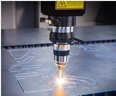
16. Laser Cutter HeadA CNC laser cutter is a
machine that uses a high-powered laser beam to mark, cut, or engrave materials,
forming customized profiles. It operates through a non-contact, thermal-based
process. The laser cutter consists of a laser head, which contains a lens assembly
and a nozzle. The laser beam, a column of intense light, is focused on the
workpiece, melting it to create the desired form. Compressed gas is used to
cool the lens and remove vaporized metal from the workpiece. The three most
commonly used types of laser cutters are CO2 laser cutters, Crystal laser
cutters, and Fiber laser cutters.
CO2 laser cutters utilize
carbon dioxide as the active laser medium. Due to their high power output and
efficiency, they are the most commonly used type. They are ideal for cutting
precise angles, especially in sheet metals, and can also produce good cut
quality on thicker metal surfaces. Fiber laser cutters use a diode bank and a
fiber-optic cable to create and focus the laser beam. They provide faster and
cleaner cutting compared to CO2 laser cutters. Crystal laser cutters employ
beams generated by crystals like neodymium-doped yttrium aluminum garnet (Nd:
YAG) and neodymium-doped yttrium ortho-vanadate (Nd: YVO). They offer higher-intensity laser power than CO2 laser cutters. The image below shows a typical
laser cutter head used with a CNC machine.
17. Water jet Nozzle
CNC water jets utilize
high-pressure water to cut various materials. Water alone is used for cutting
soft materials like wood and rubber, while water mixed with an abrasive
substance like garnet or aluminum oxide is used for cutting hardened materials.
A water jet nozzle directs a thin stream of high-speed water, sometimes
containing sharp rock pieces, to bombard the material being cut. The nozzle
connects to a high-pressure water pump that supplies it with sufficient
pressure. To reduce noise and splash, the water pressure is typically
maintained between 20,000 and 55,000 PSI. The cutting process usually takes
place underwater. The nozzle is integrated with multi-axis motion equipment,
where the head is mounted on a robotic arm. Water is supplied to the water jet
unit using a high-pressure pump and filter. The filtering process is critical
as only clean water can achieve the ultra-high pressure required for a consistent
cutting stream. The image below shows a typical water jet nozzle used with a
CNC water jet cutter.
18. Electrical Discharge Machining
Electrical Discharge
Machining (EDM) is a process where electrical energy is used to erode workpiece
material. It involves generating high-frequency sparks between an electrode
(made of Brass, Copper, Tungsten, etc.) and an electrically conductive
workpiece. As the sparks leap from the electrode to the workpiece, they carry
away tiny particles, which are flushed away by a dielectric fluid. Dielectric
fluid, usually a specialized non-conductive oil or deionized water, is used in
this process. There are three common types of EDM: Wire EDM, Hole Drills EDM,
and Sinker EDM, all of which work on the same principle. Flushing is a crucial
part of the EDM process. Inefficient flushing can lead to short circuits,
resulting in poor part quality and potential damage to the electrode.
Wire-cut EDM employs a
continuous feed of copper or brass alloy wire that passes through the workpiece.
The wire diameter typically ranges from .004 inches to .012 inches and is
widely used in the tool and die industry for cutting small slots. Hole Drilling
EDM involves a tubular electrode through which dielectric fluid flows. Graphite
or copper is commonly used as the electrode in Sinker EDM, and it is often
machined to mirror or reverse the workpiece shape. The image below shows a
typical EDM system.
19. Plasma Torch Head
Plasma cutting is a thermal
cutting process that utilizes ionized gas to cut metal. Plasma is created by
subjecting a gas, such as compressed air or nitrogen, to intense heating. The
gas is transformed into plasma, which is an electrically conductive ionized
substance. A plasma cutter uses ionized gas, typically combined with
compressed air, to generate a plasma stream. When the plasma arc contacts the
metal, its high temperature melts the metal, and high-speed gases blow away the
molten material.
CNC plasma cutters commonly
employ the Pilot arc method. In this method, a spark is formed inside the torch
by a high voltage, creating a small amount of plasma. The actual cutting arc is
formed when the pilot arc makes contact with the workpiece. A plasma torch
head, equipped with a spring-loaded mechanism, presses against the workpiece to
establish a short circuit and initiate the current flow. The image below shows
a plasma torch head used in a CNC plasma cutter machine.
20. Robotic Arm
Robotic arms are programmed
to perform specific tasks quickly and accurately. They consist of joints,
articulations, and manipulators that work together similar to a human arm.
Various types of robotic arms are available, each designed with specific
capabilities and functions for particular industrial requirements. The most
common types of robotic arms used in machining industries are Cartesian, Delta,
Fast Pick, and Collaborative Robotic Arms.
A Cartesian robotic arm has
three principal linear axes at right angles to each other, along with three
sliding joints to move the wrist up-down, in-out, and back-forth. Delta robotic
arms, with their three to four lightweight arms extending downward from the
main robot body, are commonly used in pick-and-place and packaging applications.
Fast-pick robotic arms operate at high speed for lifting objects from one
location and placing them in another. Collaborative robotic arms are capable of
learning multiple tasks and working safely alongside human workers in shared
workspaces. The image below shows a typical robotic arm used with a CNC
machine.