Thursday, December 23, 2021

Servo Motor & Amplifier

Servo System in CNC:

A servo system in CNC is a control system that regulates the velocity and position of a motor based on feedback signals. A typical CNC servo system consists of a motor, a feedback device, and a controller. The servo amplifier receives a "Reference input" (typically generated by a CNC controller) and converts it into an integral voltage, which turns the servo motor on. The servo amplifier generates the required voltage for the motor unit to achieve the expected speed. The voltage generated by the amplifier unit is called PWM or Pulse Width Modulated voltage, and both the amplitude and frequency can be adjusted by the servo amplifier unit.


A feedback device such as an encoder or resolver is attached inside the servo motor shaft and sometimes connected to an external device rotated by the motor. The feedback device converts the displacement of the motor shaft or external device into an electrical signal, which is sent to an "Error detector" circuit inside the servo amplifier. The error detector circuit compares the reference input and the encoder feedback signal. Any error detected by this comparison triggers a directive to the amplifier unit, adjusting the amplitude or frequency of the voltage supplied to the motor. Every servo system monitors both the position and velocity of the motor unit and two separate error detectors work together for Velocity and Positioning control. It always operates in a closed-loop system, and the complete system is referred to as a servo-controlled mechanism.


Servo Motor:

A servo motor is an electromechanical device commonly used to drive CNC machine axes and spindles. These motors provide higher torque with lower current consumption compared to conventional motors. They are also smaller in size and offer higher efficiency. Both DC and AC servo motors are employed, and they are sometimes referred to as control motors because they control the mechanical transmission system. Servo motors always work with a closed-loop servo system. While CNC machines previously used both types of servo motors, AC servo motors now have many advantages over DC servo motors, and most CNC machines currently use AC servo motors exclusively for spindle and axis movement. 


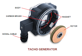
A feedback element such as an encoder, tacho generator, or resolver is always integrated with a servo motor. In the past, servo motors were equipped with two separate devices coupled to the motor shaft: one for position feedback (encoder) and another for velocity feedback (tacho generator). Nowadays, an encoder or a resolver functions as a single feedback device, providing both position and velocity feedback of the motor shaft. In some cases, an electromechanical "Brake" unit is coupled inside the servo motor, specifically for vertical axis applications, to hold the axis in place when the machine is turned off.

 Working Principle of an AC Servo Motor:

The operational principle of an AC servo motor differs from that of an AC induction motor. In an AC servo motor, a "Permanent magnet" is used to generate a magnetic field inside the motor, and the torque is produced by the current passing through it. Since AC servo motors don't have brushes, the rotation is silent, and no noise is generated. The Stator part of an AC servo motor consists of a core and winding, while the Rotor part includes a Shaft, Rotor core, and Permanent magnet. A Servo drive or Amplifier supplies the required voltage to the stator windings to rotate the servo motor shaft. The core part of the stator is designed to accommodate more windings compared to an ordinary induction motor. Special winding techniques or arrangements like "Divided core" or "Centralized winding" are used for this purpose. The Finite Element Method (FEM) is currently employed to construct servo motors, reducing "Torque ripple" and "Cogging torque" and resulting in smaller motor sizes. The following picture illustrates a typical AC servo motor and its interior.

The rotary part of a servo motor is composed of a shaft, rotor core, and permanent magnet. The magnetism capacity of the permanent magnet determines the motor's potential. Therefore, selecting the appropriate permanent magnet is crucial to limit cogging torque on the motor shaft. An optical type or a magnetic type digital encoder is commonly used for the motor's feedback system. The Optical type encoder is more prevalent and offers higher resolution compared to the magnetic type.

Servo Amplifier:

The primary function of a CNC machine is to precisely control the movements of axes and spindles. This is achieved using a Servo Drive or Amplifier unit inside the CNC machine. The servo drive mechanism consists of a Servo motor, a Servo amplifier, and a Mechanical Transmission System such as a ball screw and nut mechanism. The CNC Controller sends a command signal to the servo amplifier, which generates the required voltage to rotate the motor according to the commanded signal. The servo motor rotates the ball screw, connected to the axis shifting mechanism, to achieve the desired axis position or rotate the spindle at the required RPM. The fundamental objective of using a servo amplifier is to provide the necessary power to the servo motor for precise and secure spindle rotation or axis positioning based on the commands from the CNC Controller. In metal cutting milling machines, a cutting tool is rotated at high RPM while the workpiece is driven at a lower speed to remove material. The spindle requires constant power, while the axis requires constant torque for accurate operation. This is achieved using a microprocessor-based servo amplifier, which provides precise control over speed and torque for axis and spindle movements in CNC machines.

There are two main types of servo amplifiers used in CNC machines: Axis or Feed servo amplifiers and Spindle servo amplifiers. Feed servo amplifiers provide continuous torque for axis movements, while spindle servo amplifiers offer constant power for spindle rotation. It is common to use separate servo amplifiers for different axis movements and spindle rotation. AC servo amplifiers are generally preferred over DC servo amplifiers. The following pictures show AC servo amplifiers in operation with CNC machines.

Spindle servo amplifier: Spindle servo amplifiers are used for high rotational accuracy, constant power output, smooth running, fast dynamic response, and a wide speed range for spindle rotation. There are two types of spindle servo amplifiers: DC and AC. DC spindle amplifiers were used in earlier CNC machines to provide constant power to the machine spindle assembly. However, microprocessor-based AC servo amplifiers are now widely used in most types of CNC machines due to their numerous advantages. One great advantage of using an AC servo amplifier is that the spindle can be considered as a 'C-Axis'.


Feed servo amplifier: Feed servo amplifiers are responsible for driving the axis servo motors in a CNC machine. The number of feed servo amplifiers in a CNC machine is equal to the number of controlled axes. Feed servo amplifiers always operate on constant torque, and position feedback also plays a significant role in the amplifier unit. In contouring operations where two separate axes require synchronized movement to create a circular path (arc type), feed amplifiers work together harmoniously.


How does a DC servo amplifier work?

A DC servo amplifier, also known as an SCR-DC drive, uses a Silicon Controlled Rectifier (SCR) to supply the necessary voltage to run a DC motor. The SCR or thyristor is a solid-state device with three terminals: Anode, Cathode, and Gate. The reference input signal from the CNC Controller is sent to the control card of the amplifier unit, which generates a positive firing pulse to trigger the SCR by applying it to the Gate terminal. This triggers a current flow between the Anode and Cathode terminals, which continues until the anode voltage of the SCR is withdrawn or the polarity of the firing pulse changes. The average DC voltage generated by a DC servo amplifier controls the motor's operation by adjusting the firing pulse angle sent to the thyristor's Gate terminal. By controlling a small amount of gate voltage, greater power can be easily controlled. The following picture shows the block diagram of a DC servo drive system.

How does an AC servo amplifier work?

Most CNC machines nowadays use AC servo amplifiers exclusively. The rotational speed or RPM of an AC motor is directly proportional to the frequency of the AC mains and the number of poles inside the motor. This relationship is defined by the formula n = 20f / p, where n represents the motor speed, f is the frequency of the supply line, and p is the number of poles in the motor. Therefore, for a motor with a fixed number of poles, the RPM depends solely on the frequency of the input supply. To maintain a constant torque within a specific speed range, the V/f ratio (voltage to frequency) of any motor must be kept constant. The V/f ratio is determined by the AC RMS voltage (V) and the frequency (f) of the AC voltage line. An AC servo amplifier maintains a constant V/f ratio in order to achieve a constant torque within a specific speed band of an AC servo motor.

An AC servo amplifier changes the supply voltage frequency to the servo motor, thereby achieving variable speed. Inside an AC servo amplifier, a three-phase AC input voltage is converted into DC voltage using a converter circuit. This DC voltage is then converted back into three-phase AC with an adjustable frequency using various switching mechanisms within the servo amplifier. Finally, the AC voltage with adjustable frequency is supplied to the motor coil. An AC servo amplifier is sometimes referred to as an 'Inverter' unit. The following picture shows a simplified block diagram of an AC servo amplifier.


Most AC servo amplifiers employ a Pulse Width Modulation (PWM) control system to change the output voltage frequency. A PWM control servo amplifier consists of two main parts: the Converter section and the Inverter section. The Converter section converts the three-phase AC into a fixed DC voltage using a rectifier unit. The DC voltage from the converter section is then filtered to obtain a constant and ripple-free DC voltage. This constant and ripple-free DC voltage is further supplied to the inverter section of the amplifier.   


The inverter section of the servo amplifier generates an AC output voltage that is supplied to the servomotor. A series of voltage pulses are generated to form a sine wave by positive and negative switching inside the inverter section. The output frequency of the PWM voltage is controlled by sending positive and negative pulses on either side of the voltage halves. The amplitude of the output voltage is determined by the width of each pulse, representing either a lower or higher voltage value. This method of generating lower or higher output voltage pulse widths is called 'Pulse Width Modulation' for PWM control. The earlier picture shows only six pulses with every half cycle of the voltage. To achieve a specific frequency for the output voltage, an optimal number of pulses and pulse widths are created so that the output voltage closely approximates a pure sine wave.

In some cases where multiple servo amplifiers are used with CNC machines, a single power converter unit is employed to supply a DC voltage to a common DC bus, instead of using separate power converter units for each amplifier module. The inverter sections of all the amplifiers receive the required DC voltage from the common DC bus. The following picture shows three servo amplifiers connected to a single power converter unit. 


The braking system in the servo amplifier:

Almost every servo amplifier incorporates a braking system, which plays a crucial role in the axis and spindle movements of a CNC machine. Servo motors need to hold the axis or spindle in a commanded position and stop within a certain distance during a power failure or emergency state. Otherwise, they may overshoot the desired movement. A braking arrangement is employed with a servo drive to overcome this situation and ensure the axis or spindle stops at the correct position. There are two types of braking systems: Dynamic braking and Regenerative braking.

Dynamic Braking - In this method, the armature coil ends of the servo motor are connected to a Dynamic Braking Resistor (DBR) via a contactor during the braking condition. The kinetic energy stored inside the rotating motor is converted into heat within the dynamic braking resistor, which applies reverse torque to the motor movement and helps bring it to a stop. This type of braking system is particularly useful in the event of a power failure or emergency state of a CNC machine.

Regenerative Braking - The servo amplifier utilizes a sequence of firing pulses to implement a regenerative braking system. This short duration of firing pulses causes the phase sequence of the power supplied to reverse momentarily, effectively stopping the motor quickly. A ramp network circuit is always employed with the servo amplifier to prevent damage to the motor coil and sudden changes in the motor supply sequence. The regenerative braking system is applicable only to fully controlled servo amplifiers.


Wednesday, December 15, 2021

Stepper Motor & Driver

Stepper Motor: 

A stepper motor is a brushless synchronous motor that splits 360-degree shaft movement into multiple steps, allowing for precise speed control. It gets its name because the motor shaft moves in discrete steps with each electrical pulse. Typically, a stepper motor works in conjunction with a driver unit that generates electrical pulses to rotate the motor shaft. The speed of the stepper motor is determined by the frequency of these electrical pulses. The following picture shows the interior of a stepper motor. 


Stepper motors are usually classified into three types: variable reluctance, permanent magnet, and hybrid. The motor features a magnetic or toothed soft iron rotor that rotates within an electromagnetic field (see picture). By energizing the stators through a motor driver unit, a torque is applied to the rotor, causing it to rotate while maintaining a minimum gap between the stator coils and the rotor teeth or magnetic poles. When the stator coils are energized in a fixed sequence, the stepper motor shaft exhibits continuous rotary movement. The following pictures illustrate this phenomenon. The coils A-A', B-B', C-C', and D-D' are successively energized (indicated by the dark color), resulting in a 15-degree step movement of the motor shaft. 


Stepper Motor Driver:

A stepper motor driver is an electronic device used to control a stepper motor. The driver generates the appropriate signals from the input data to move the motor axis. The most common method for driving a stepper motor is using an H-bridge. This circuit consists of four FET transistors that have low resistance between the drain and source contacts in an inactive state. Since the stepper motor requires a minimum of two coils, at least two H-bridges are needed. By controlling the current direction through the motor coil and providing individual signals to the FET gates, the motor axis can be shifted. Most stepper motor drivers receive Step and Direction input signals from the controller, requiring only two signals for each driver. Each pulse indicates that the stepper motor will move one step, while the direction signal determines the direction (clockwise or counterclockwise) in which the stepper motor will turn. The driver is controlled by the controller using a standard communication protocol such as MODBUS or USB. The following picture illustrates the different connections between the stepper motor and the driver unit.


Stepper Motor Usage in CNC Machines:

Stepper motors are widely used in CNC machines to control various axes. They are commonly employed in CNC routers, CNC plasma cutters, and other machines operating on an open-loop control system, where precise positioning is not critical. In such cases, the stepper motor's lower positioning accuracy is acceptable. For precise CNC machining operations, servo motors are preferred. However, due to their lower cost compared to servo motors, stepper motors are often used in low-budget CNC machines. The picture below illustrates the different connections between stepper motors, drivers, and controllers in a CNC router machine.


Thursday, December 2, 2021

Feedback Elements

A feedback element is a precise measuring tool used to measure the linear or angular position, displacement, and sometimes speed in a mechatronics system. These tools continuously send the current position information of a moving object as an electrical signal to the CNC Controller and obtain the actual position and velocity information. Measuring equipment can be categorized into two primary groups: rotary measuring tools (such as Encoder, Resolver, and Tacho generator) and linear measuring tools (such as Linear scale and linear Inductosyn). The function of measuring devices is to generate a constant electronic signal and send it to the Controller. The following are some commonly used measuring devices found in different mechatronics systems.

Optical Encoder:

The optical encoder is the most commonly used rotary-type measuring device in mechatronics systems. It relates the actual position and speed of an element, such as the state of an axis or spindle speed feedback with CNC machines. An encoder is usually integrated inside a servomotor, coupled with the motor shaft, and sometimes separately attached to a ball screw or spindle unit with a timing belt. Inside an optical encoder, a graduated glass disc is attached to a shaft, which rotates freely along with the disc. The glass disc has opaque and transparent portions. Photo-electric cells and light sources are placed on either side of the disc, allowing the light to pass through and strike the photo-electric cells. As the servo motor shaft or ball screw rotates, the encoder shaft, attached to it, also rotates. Due to the transparency and opaqueness of the glass disc, the light emitted from the source sometimes reaches the photo-electric cell and sometimes does not. The output signal from the photo-electric cells is passed through an electronic circuit, where it is converted from a sinusoidal signal to a rectangular waveform, and then transmitted to the Controller via a signal cable. There are two types of optical encoders used with CNC systems: Incremental Rotary Encoder and Absolute Rotary Encoder. The following picture shows an optical encoder widely used with CNC systems. 


Incremental rotary encoder - Incremental measurement refers to computation by counting. The output signal of an incremental rotary encoder is sent to an electronic counter inside the Controller. Each increment of the output signal contributes to the comprehensive measurement. The following picture illustrates how an incremental rotary encoder works.

The main difference between an incremental rotary encoder and an absolute rotary encoder lies in the structure of the graduated glass disk inside the encoder. In the previous picture, the gratings of the graduated glass disc in an incremental encoder are marked radially, within a range of 200 PPR (parts per revolution) to 18000 PPR. The output PPR of an incremental rotary encoder indicates the number of pulses it will generate with a 360-degree rotation of the Encoder shaft, depending on these gratings on the glass disc. Here is another grating mark for reference, which is only marked in one place on the graduated glass disc, indicating the starting point of the measurement counting.

Absolute Rotary Encoder- The fundamental working principle of an absolute rotary encoder is similar to that of an incremental rotary encoder, with the only difference lying in the construction of the glass disc (refer to the picture below). In an absolute encoder, multiple tracks are built over a glass disc instead of a single track as seen in an incremental encoder. Each track consists of transparent and opaque sections arranged in a specific manner using a different technique. The composite signals received from the photoelectric cells become unique for a particular position of the encoder shaft. This means that the combined signals from the photoelectric cells for different states of the encoder shaft (ranging from 0 to 360 degrees) also differ sequentially. The unique position of the encoder shaft is typically defined using binary or Gray code. The image below illustrates a typical structure of grating marks on a glass disk of an absolute rotary encoder.

Magnetic Encoder:

Typically, an optical encoder consists of a glass disc and cannot be used in various mechatronics systems that involve vibration, extreme heat, or humidity. It is highly inconvenient to use an optical encoder with a glass disc in such scenarios. On the other hand, a magnetic encoder performs exceptionally well in harsh and stressful environments, providing accurate feedback. This type of encoder utilizes Hall Effect technology, and both rotary and linear magnetic encoders are compatible with CNC systems.

 A magnetic rotary encoder consists of three main components: a magnetic disk, a sensor, and a conditioning circuit. The encoder disk is composed of small magnetic poles arranged in alternating North and South poles along its circumference. As the disk rotates, a sensor inside the Sensing Head converts the magnetic field signal into a Sine wave. The encoder sensor commonly uses a Hall Effect device or, in some cases, a Magneto-resistive element. The signals from the sensor pass through a Conditioning circuit, which converts them into a format understandable to the CNC Controller. The sensor and conditioning circuit are usually integrated inside the sensing head and connected to the controller through a signal cable. The fundamental working principle of a linear magnetic encoder is similar to that of a rotary magnetic encoder, except that a Magnetic tape is used instead of a magnetic disk (refer to the picture), with alternating magnetized poles spread across the tape.

Linear Scale:

A linear scale, also known as a linear encoder, precisely measures the linear displacement of an object, such as the linear axis movements of a CNC machine. In CNC machines, a linear scale is typically installed along the machine slide to provide accurate and precise position measurements, compared to those obtained from an encoder usually fixed with a motor shaft. There is always a certain amount of backlash present when converting linear displacement into rotary movement (like that of a motor). Therefore, a linear scale offers better accuracy compared to an encoder.

A linear scale consists of two separate units: a glass scale and a reading head. One of these units, either the glass scale or the reading head, is attached to the moving body, while the other remains stationary. The glass scale is similar to an encoder's glass scale and is fabricated with alternating transparent and opaque gratings. The reading head contains a light source, lens, scanning reticle, and photo-electric cells, similar to an encoder. When the reading head moves over the glass scale, the transparent and opaque grating parts align with the scanning reticle index alternately. This causes the light passing through the lens to reach the scanning reticle and glass scale, eventually falling on the photo-electric cells. As a result, the photo-electric cells generate a sinusoidal signal based on the fluctuations of light. The sinusoidal signal is then converted to a rectangular waveform using an electronic circuit within the reading head and sent to the controller via a flexible cable.

Resolver:

A resolver is a rotary measuring device that provides position and velocity feedback of a rotating device. It consists of a motor shaft and is used to obtain information about the rotating device's position and velocity. The resolver is composed of two stator windings and a rotor winding. The stator windings are wrapped in such a way that there is a 90° phase shift between them. The rotor and stator windings function as primary and secondary windings of a transformer and are assembled inside the resolver. When a sinusoidal signal passes through the stator windings with a 90-degree phase shift, a sinusoidal signal is induced in the rotor winding. As the rotor shaft rotates, the output signal changes in accordance with the reference signal, and the magnitude of the output signal depends on the rotation of the resolver shaft. The output signal phase changes from 0° to 360° as the resolver shaft rotates continuously. Since controllers only recognize digital information, the resolver's output signal is converted into a digital signal before being sent to the controller. The following image shows a resolver commonly used in CNC systems.


Tachogenerator:

A tachogenerator is a rotary measuring device used to obtain speed feedback from a rotating element. It was commonly found in earlier mechatronics systems, but nowadays, optical encoders transmit both speed and positional feedback, making the use of tachogenerators almost obsolete. A tachogenerator is a simple permanent magnet DC generator typically installed with a servomotor or a rotating object shaft. It produces a DC voltage that serves as the signal output. The analog DC voltage generated by the tachogenerator changes with the motor's RPM, and the controller receives this information by measuring the analog voltage, and determining the speed or RPM of the motor. The following picture shows a simple DC tachogenerator.

Inductosyn:

Inductosyn is a type of analog precision measuring equipment and is considered one of the most accurate position-measuring devices in the world. There are two main types of Inductosyn: linear and rotary. The linear type consists of a scale and a slider, while the rotary type includes a rotor and a stator. Inductosyn is commonly used for high-accuracy measurements and operates effectively in harsh environments. One advantage of using a linear Inductosyn over a linear scale is that the scale is easily expandable and suitable for measuring over long distances.

The operating principle of an Inductosyn is similar to that of a multi-pole wire-wound resolver. In a rotary Inductosyn, the rotor and stator have printed circuit patterns that function as two windings in a rotating transformer. An AC signal is applied to the rotor winding, inducing a current in the stator winding as the rotor rotates relative to the stator. The output amplitude varies in a cyclic sinusoidal pattern, providing a signal output. This output signal is then amplified and transmitted to an Analog-to-Digital converter circuit to obtain a reliable output signal for the controller.

A linear Inductosyn can be thought of as a resolver that has been unwound on a flat surface. In this case, the scale of a resolver is represented by the Inductosyn scale, which is typically placed on a machine bed, while the rotor of a resolver is equivalent to the slider of a linear Inductosyn. The slider moves over the scale, maintaining a small gap (usually 200 microns). Similar to a resolver, the slider in an Inductosyn also contains two windings. A sinusoidal voltage is applied to these windings with a 90-degree phase difference, and the induced voltage in the windings is considered as the signal output. The induced voltage is usually low (microvolts), so an appropriate pre-amplifier is always used with Inductosyn to amplify the voltage, enabling direct interfacing with the controller.


Popular Posts